Neon lights have inspired much prose over the years, with their attractive light output receiving glowing adulation. [Pierre Muth] is a big fan, and decided to spend lockdown creating something suitably pretty for his desk.
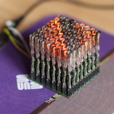
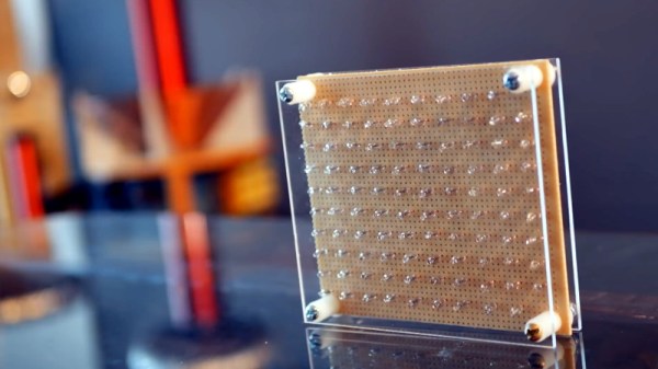
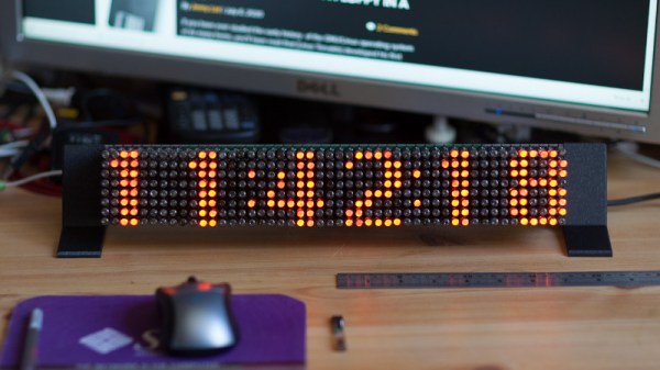
The project consists of an 8×48 matrix display constructed out of INS-1 (ИНC-1) tubes. These tiny neon tubes are 6.5 mm in diameter, showing a bright orange dot of light when powered up. Requiring just 100 V and 0.5 mA to light, they’re a touch easier to drive than the famous Nixie.
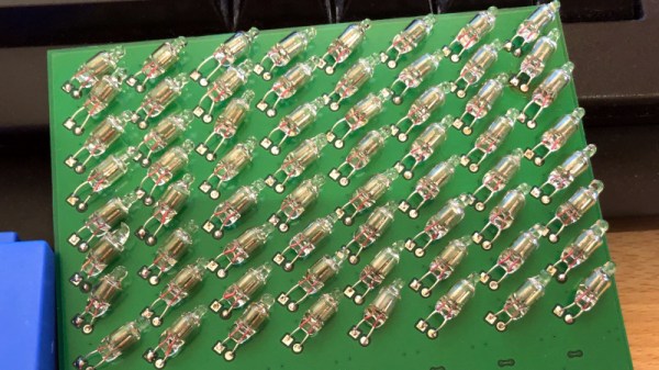
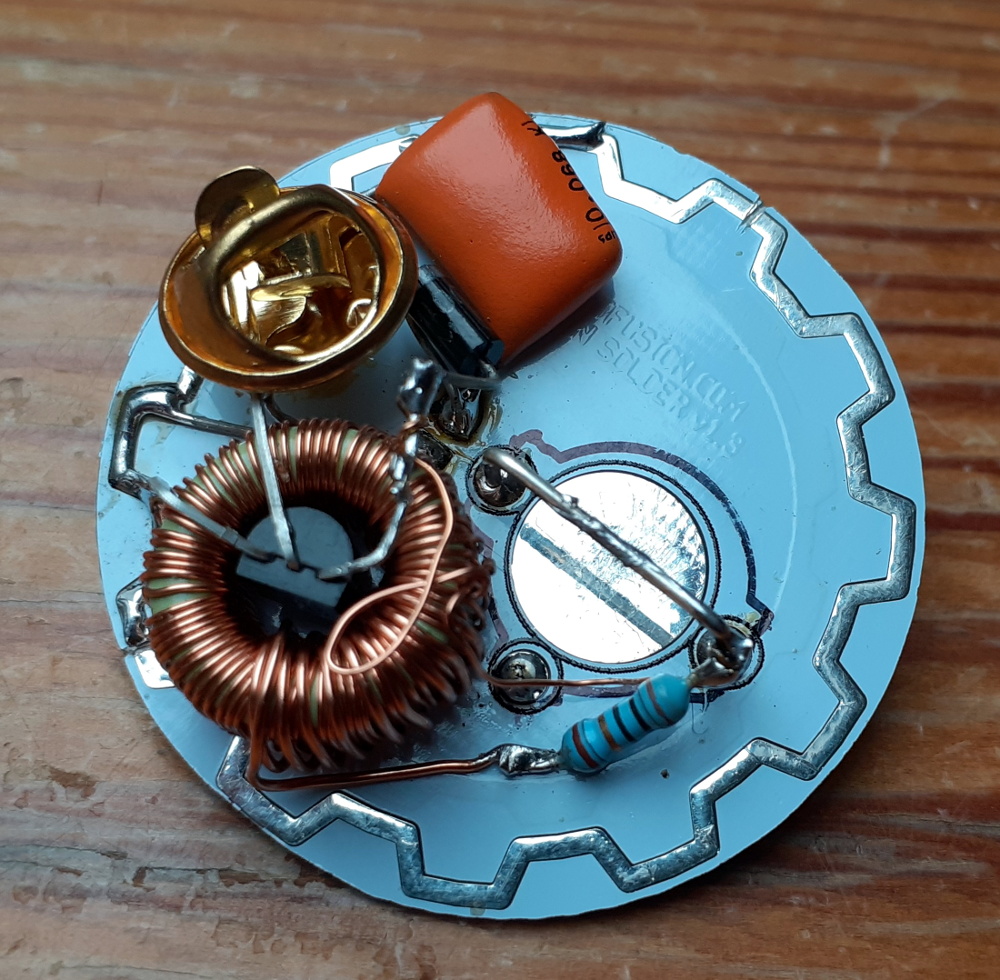
[Pierre] decided to go all out, wishing to replicate the capabilities of smart LEDs like the WS2812. These contain a microcontroller built in to each LED, so [Pierre] would have to do the same. Each of the 384 neon tubes got its own bespoke PCB, containing a PIC16F15313 microcontroller, step up voltage circuitry, and a 6-pin connector. (Whoah!) When each bulb was soldered to its PCB, they were then plugged into a backplane. An ESP32 was then employed to drive the display as a whole.
Creating a display in this fashion takes a huge amount of work, with most of it being soldering the 384 individual bulb PCBs containing 11 components each. We have a lot of respect for [Pierre]’s work ethic to get this done during lockdown, and the final result is a gloriously retro neon matrix display. We’ve featured other neon matrixes recently, too. Video after the break. Continue reading “384 Neon Bulbs Become Attractive Display”