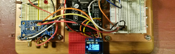
Ever wanted to own your own Theremin but couldn’t justify dropping hundreds of dollars on one? Now you can build your own, or buy it for a quintuplet of Hamiltons. The Open.Theremin.UNO project has built up antenna-based oscillator control around the ubiquitous Arduino Uno board.
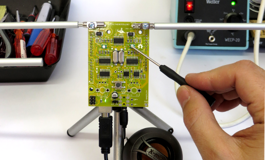
So what’s the Arduino in there for? This is a digital Theremin, but check out the video below and you’ll agree that it sounds amazing and has excellent response. The aluminum antennas used for volume and pitch are attached to the top portion of the shield but it sounds like they’re not included in the kit. Don’t fret, you can use a variety of materials for this purpose. On the bottom you need to connect a speaker cable, and also a ground wire if that cable’s not grounded.
As the name implies, this is Open Hardware and we’re quite happy with the documentation on their site and the BOM (found on the GitHub repo). This design was shown off back in 2013 hiding in a pack of cigarettes. If you don’t want to build your own they’re selling kits on their site for 48 Euro delivered, or on Tindie for $55.
Okay, we’ve screwed this up so many times that we’re going to try to get it right here: the Theremin was not heard in the opening of Star Trek the original series, or in the opening of Doctor Who. It wasn’t featured in “Good Vibrations” either. As far as we can tell, it’s not used for anything in pop culture at all… but recognizing the sound and knowing what one is remains core geek knowledge.
If you want a Theremin to play using your entire body you need the Theremin Terpsitone.
Continue reading “Finally, A Modern Theremin” →