Fiber Laser Gives DIY PCBs A Professional Finish

While low-cost professional PCB fabrication has largely supplanted making circuit boards at home, there’s still something to be said for being able to go from design to prototype in an afternoon. Luckily we aren’t limited to the old toner transfer trick for DIY boards these days, as CNC routers and powerful lasers can be used to etch boards quickly and accurately.

But there’s still a problem — those methods leave you with a board that has exposed traces. That might work in a pinch for a one-off, but such boards are prone to shorts, and frankly just don’t look very good. Which is why [Mikey Sklar] has been experimenting with applying both a soldermask and silkscreen to his homemade boards.

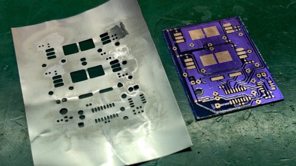
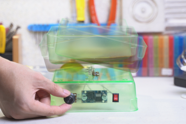
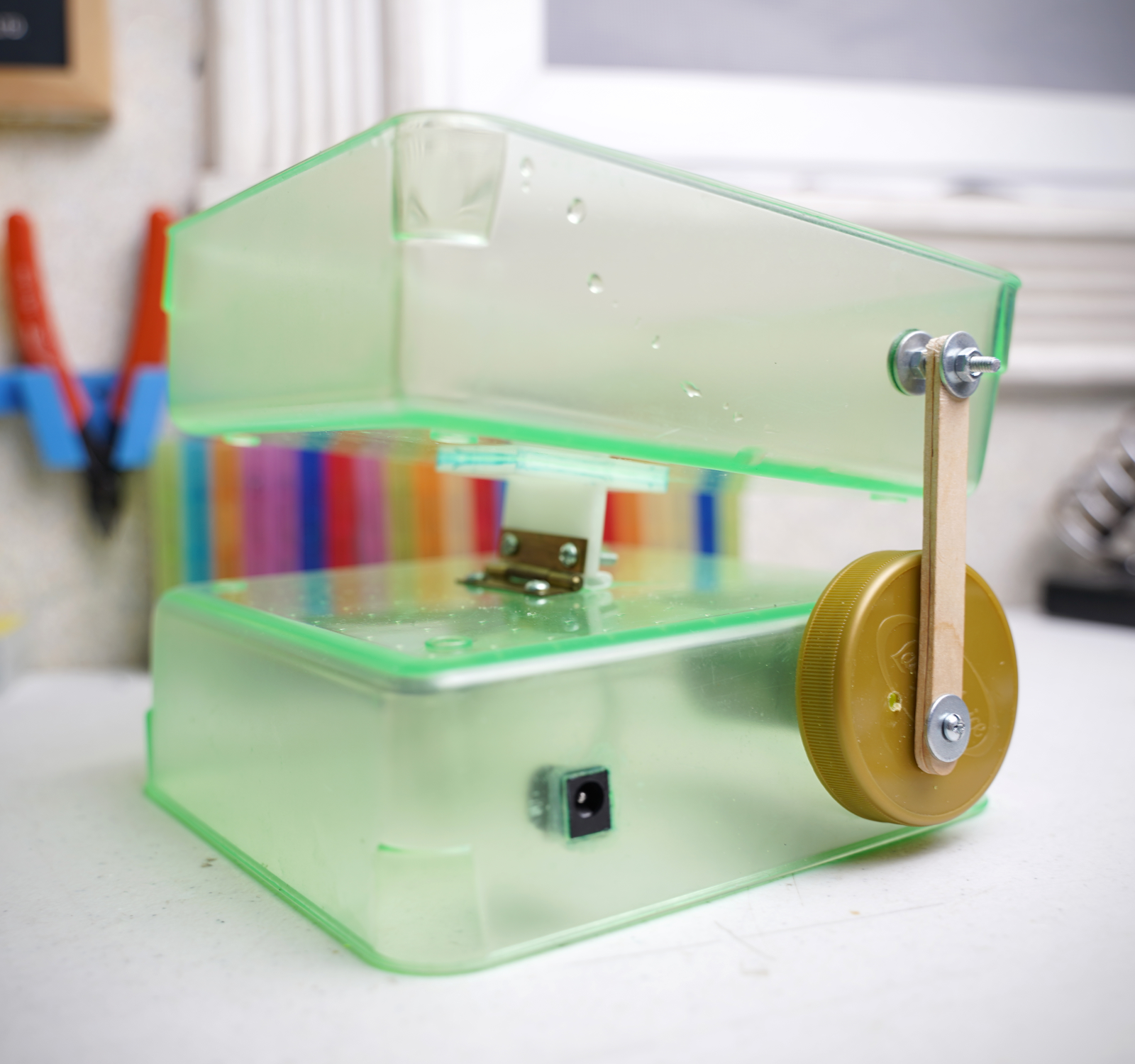
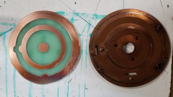
The process he describes starts after the board has already been etched. First he rolls on the soldermask, and then sandwiches the board between layers of transparency film and clear acrylic before curing it under a UV light. After two coats of the soldermask, the board goes into a fiber laser and the silkscreen and mask layers are loaded into the software and the machine is set to a relatively low power (here, 40%). The trick is that the mask layer is set to run four times versus the single run of the silkscreen, which ensures that the copper is fully exposed.

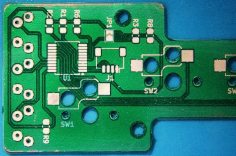
Since the board doesn’t need to be moved between operations, you don’t have to worry about the registration being off. The end result really does look quite nice, with the silkscreen especially popping visually a lot more than we would have assumed.

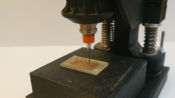
We’ve previously covered how [Mikey] uses his CNC router and fiber laser to cut out and etch the boards, so this latest installment brings the whole thing full circle. The equipment you’ll need to follow along at home isn’t cheap, but we can’t argue with the final results.

Continue reading “Fiber Laser Gives DIY PCBs A Professional Finish”

Simple PCB Agitator Gets The Job Done

These days, PCB fab houses are just about everywhere, and you can’t go buy a taco without walking past eight of them. Still, some out there still like to etch their PCBs at home. If that sounds like you, you might see some value in [Chris Borge]’s PCB agitator. 

The design mostly relies on 3D printed parts, including the main body. It has a heavy base which is filled with concrete to keep it nicely weighed down on the table. A table for holding a PCB and fluid tank is then installed on top, via a bearing which allows it to pivot in one axis. An Arduino Nano commands the agitation of the table top, and hence the PCB etching tank, with a servo used to actually shift the table back and forth.

It’s a simple design — far simpler than some of the advanced coffee-making hardware we’ve seen recently. Regardless, it gets the job done, and done well! In testing, it accelerated [Chris]’s etching jobs significantly, we’re talking hours here. Meanwhile, if you don’t have a 3D printer on hand, you could always try building one out of junk instead!

Continue reading “Simple PCB Agitator Gets The Job Done”

RC Car Repair With Beer Can Solder Stencil

Sometimes it might seem as if your electronics are just jinxed. For [Niva_v_kopirce] it was the control board of his nephew’s RC car that kept frying the transistors. In situations like this, you can either throw it in the bin, invest your time in troubleshooting, hoping to find the error and try to fix it then, or get creative. He chose the latter, and designed and etched a replacement board.

Of course, etching your own PCB isn’t that noteworthy for the average Hackaday reader, although [Niva_v_kopirce] did go the extra mile and added purple solder mask to it, turning the stylishness definitely up to 11. This is also where it gets interesting, when you think of the solder mask as complementary layer for a solder paste stencil. Growing tired of manually applying solder paste, he thought to give a DIY stencil a try this time — using a beer can.

After cutting the can open and flattening it, along with some sanding, he transferred the cutouts from the solder mask onto it, and started etching holes in it. While the result may not be exactly precise, it did the job, especially for a homemade built.

Despite their convenience, stencils are still a rather exotic addition for hobbyists as they rarely pay off for a one-off project with limited SMD component usage. But maybe this was a new inspiration for you now. And if etching metal is outside your comfort zone, cutting plastic can be an alternative, as well as 3d printing.

Now This Is A Maker’s PCB Shaker

Anyone who has ever etched their own PCB knows that the waiting is the hardest part. Dissolving copper in ferric chloride takes time, much like developing a Polaroid picture. And although you really should not shake a fresh Polaroid to speed up development, the PCB etching process thrives on agitation. Why wait an hour when you can build a simple PCB shaker and move on to drilling and/or filling in 10 minutes?

We love that [ASCAS] was probably able to build this without reaching past the the spare parts box and the recycling bin. There’s no Arduino or even a 555 — just a 12 VDC geared motor, a DC-DC buck converter, and an externalized pot to control the speed of the sloshing.

It’s hard to choose a favorite hack here between the hinge used to rock this electric seesaw and the crankshaft/armature [ASCAS] made from a sandwich spread lid and a Popsicle stick. Everything about this build is beautiful, including the build video after the break.

Did you know that unlike ferric chloride, copper chloride can be recharged and reused? Here’s a one-stop etching station that does just that.

Continue reading “Now This Is A Maker’s PCB Shaker”

Print A Drill Press For Your Printed Circuit Boards

If you make printed circuit boards the old fashioned way by etching them yourself, you may need to drill a lot of holes; even surface-mount converts still need header pins on occasion. But, drilling these holes by hand often leads to broken drill bits, which always seems to happen with one un-drilled hole and no spare bits left. [Daumemo] came up with a solution: a 3D printed drill press for a Dremel or similar rotary tool.

While you can buy commercial presses designed to fit these tools, there’s a certain satisfaction to building your own, and if you have a well-stocked parts bin you might even finish it before a mail-ordered version could arrive. Certainly you could do it at lower cost. The design is straightforward, and uses printed parts augmented with “reprap vitamins” (i.e. the non-printable, typically metal, components). If you’ve ever built — or repaired — a 3D printer, you may have these pieces already: a couple of LM8UU bearings, some 8 mm steel rod, and a pair of springs seem like the most esoteric parts required, although even these could probably be substituted without much trouble.

Only a few pieces need to be printed: a base is outfitted with a removable table for holding the workpiece, while a lever actuates the frame holding the tool. [Daumemo] chose to print the design in ABS, but found that it flexes a little too much, occasionally requiring some care during use — a stiffer filament such as PLA might yield better results. Overall, though, this seems like a great project for that 3D printer you haven’t used in a while.

Be sure to check out the video of the press in action, after the break.

Continue reading “Print A Drill Press For Your Printed Circuit Boards”

Custom PCB Revives A Vintage Tree Stand

After 56 years, [Jeff Cotten]’s rotating Christmas tree stand had decided enough was enough. While its sturdy cast aluminum frame was ready for another half-century of merriment, the internal mechanism that sent power up through the rotating base had failed and started tripping the circuit breaker. The problem itself seemed easy enough to fix, but the nearly 60 year old failed component was naturally unobtanium.

But with the help of his local makerspace, he was able to manufacture a replacement. It’s not exactly the same as the original part, and he may not get another 56 years out of it, but it worked for this season at least so that’s a win in our books.

The mechanism inside the stand is fairly simple: two metal “wipes” make contact with concentric circle traces on a round PCB. Unfortunately, over the years the stand warped a bit and the wipe made contact with the PCB where it wasn’t intended do. This caused an arc, destroying the PCB.

The first step in recreating the PCB was measuring the wipes and the distance between them. This allowed [Jeff] to determine how thick the traces needed to be, and how much space should be between them. He was then able to take that data and plug it into Inkscape to come up with a design for his replacement board.

To make the PCB itself, he first coated a piece of copper clad board with black spray paint. Using the laser cutter at the makerspace, he was then able to blast away the paint, leaving behind the two concentric circles. A quick dip in acid, a bit of polishing with toothpaste, and he had a replacement board that was close enough to bolt up in place of the original hardware.

If you’d like to see the kind of hacks that take place above the stand, we’ve got plenty to get you inspired before next Christmas.

Wearable Foxhunt Transmitter For Conventions

Amateur radio operator [KE4FOX] wanted to build his own 2M fox hunt transmitter for use at conventions. It would be contained in a 1020 Pelican micro case and attached to a person who would walk around transmitting a signal, leaving the hams to track down the fox. The project uses a DRA818 VHF/UHF transceiver plugged into a low-pass filter combined with a hardware DTMF decoder, all controlled by an ATmega328P and powered by a 11.2 mAh battery.

[KE4FOX] also etched his own PCB, using the PCB toner transfer method, folding a sheet of transfer paper around the board to align both layers. Then he etched the board using cupric chloride. When assembling the board he realized he had made a terrible error, assuming the transceiver module’s pins went in the top layer when in fact they should have gone in the bottom layer. He solved this by soldering in the module in upside down.

He dropped the project into the 1020 and installed an SMA antenna. After he assembled the project he found out that the level shifter he used on the Arduino’s 5 V data didn’t work as expected and it was stuck at a single frequency. Something to work on for V2!

We publish a large number of amateur radio posts here on Hackaday, including fox hunting with Raspberry Pi and how to make a TDOA directional antenna.

[thanks, that Kat!]