Tiny PCB Motor Robot Is Making Its First Wobbly Moves

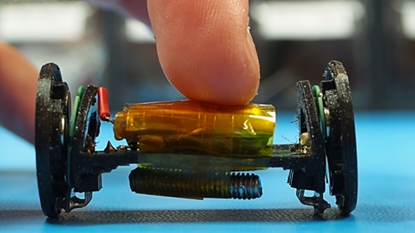
[Carl Bugeja] has been working on his PCB motors for more than three years now, and it doesn’t seem like he is close to running out of ideas for the project. His latest creation is a tiny Bluetooth-controlled robot built around two of these motors.

One of the main challenges of these axial flux PCB motors is their low torque output, so [Carl] had to make the robot as light as possible. The main board contains a microcontroller module with integrated Bluetooth, an IMU, regulator, and two motor drivers. The motor stator boards are soldered to the main board using 90° header pins. The frame for the body and the rotors for the motors are 3D printed. A set of four neodymium magnets and a bearing is press-fit into each rotor. The motor shafts are off-the-shelf PCB pins with one end soldered to the stator board. Power comes from a small single-cell lipo battery attached to the main board.

The robot moves, but with a jerking motion, and keeps making unintended turns. The primary cause of this seems to be the wobbly rotors, which mean that the output torque fluctuates throughout the rotation of the motor. Since there are only two points of contact to the ground, only the weight of the board and battery is preventing the central part from rotating with the motors. This doesn’t look like it’s quite enough, so [Carl] wants to experiment with using the IMU to smooth out the motion. For the next version, he’s also working on a new shaft mount, a metal rotor, and a more efficient motor design.

We look forward to seeing this in action, and also what other application [Carl] can come up with. He has already experimented with turning it into a stepper motor, a linear motor, and a tiny jigsaw motor.

Continue reading “Tiny PCB Motor Robot Is Making Its First Wobbly Moves”

Microstepping A PCB Motor

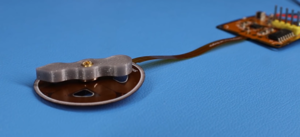
Over the last 2 years [Carl Bujega] has made a name for himself with his PCB motor designs. His latest adventure is to turn it into a stepper motor by adding position control with microstepping.

The NEMA stepper motors most of us know are synchronous stepper motors, while [Carl]’s design is a permanent magnet design. It uses four coils on the stator, and two permanent magnets on the rotor/dial. By varying the current through each of the four poles with a stepper driver (microstepping), the position of the rotor should theoretically be controllable with good resolution. Unfortunately, this was easier said than done. He achieved position control, but it kept skipping steps in certain positions.

The motor and controller consist of a single flexible PCB, to reduce the layer spacing and increase the coils’ magnetic field strength. However, this created other problems, since the motor shaft didn’t have a solid mounting point, and the PCB flexed as the stator coils were energized. Soldering the controller was also a problem, as the through-hole headers ripped out easily and the PCB bulged while reflowing on a hot plate, in one case even popping off components. [Carl] eventually mounted one of the PCB motors inside a 3D printed frame to rigidly constrain all the motor components, but it still suffered from missed steps. Any suggestions for fixing the problem? Drop them in the comments below.

Like his other PCB motors, the torque is very low, but should be suitable for gauges or clocks. A PCB clock with an integrated motor would be pretty cool to have on the workshop wall.

The TMC2300 stepper driver [Carl] used belongs to the same family of drivers that enable silent stepping for 3D printers. We’ve covered a few of [Carl]’s PCB actuator adventures, from his original design to linear actuators and a flexible POV display.

Continue reading “Microstepping A PCB Motor”

Hackaday Podcast 027: Confusingly USB-C, Glowey Displays, Logically VGA, Hackers Who Changed Gaming

Hackaday Editors Elliot Williams and Mike Szczys dive into the most interesting hacks of the week. Confused by USB-C? So are we, and so is the Raspberry Pi 4. Learning VGA is a lot easier when abstract concepts are unpacked onto a huge breadboard using logic chips and an EEPROM. Adding vision to a prosthetic hand makes a lot of sense when you start to dig into possibilities of this Hackaday Prize entry. And Elliot gets nostalgic about Counter-Strike, the game that is a hack of Half-Life, grew to eclipse a lot of other shooters, and is now 20 years old.

Take a look at the links below if you want to follow along, and as always tell us what you think about this episode in the comments!

Take a look at the links below if you want to follow along, and as always, tell us what you think about this episode in the comments!

Direct download (60 MB or so.)

Continue reading “Hackaday Podcast 027: Confusingly USB-C, Glowey Displays, Logically VGA, Hackers Who Changed Gaming”

Circular Linear Motor Becomes A Micro Motor Raceway

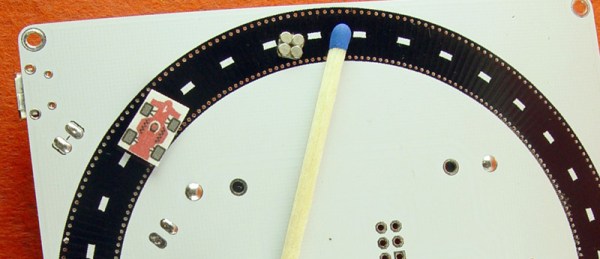
Over on Hackaday.io we have a lot of people playing around with the possibilities presented by cheap printed circuit boards. Whether that means making a quadcopter from fiberglass or a speaker from etched copper, we’ve seen just about everything. Now, finally, we have a miniature magnetic racetrack. It’s an ant highway, or a linear motor wrapped around into a circle. Or a tiny-scale model railroad. Either way it’s very, very cool.

The ant highway comes from [bobricius], one of the many makers tinkering around with coils and traces. This time he’s built a ten centimeter square board that is, effectively, a linear motor. It’s a three-phase motor made out of PCB coils, with a small magnetic ‘car’ that’s pushed forward. These coils are controlled by an ATtiny10 and a trio of MOSFETs. Wrap that linear motor into a circle and you have a neat little circular track that’s the smallest model car raceway you’ve ever seen.

As with all of [bobricius]’ circuit boards, this one demands a video, and that’s available below. This is an interesting bit of technology, and it’s more than just a raceway for tiny magnetic cars. This could be the beginnings of an analog clock with a digital heart, or the start of the smallest model train layout you’ve ever seen. There’s impressive work being done with PCB motors now that printed circuit boards are so cheap, and we can’t wait to see what’s next.

A quick Hackaday search will reveal [bobricius] as a prolific source of projects whose work we’ve featured multiple times. Favorites include a brushless PCB motor, and an FR4 cell phone.

Continue reading “Circular Linear Motor Becomes A Micro Motor Raceway”

Hackaday Podcast 008: The Art Episode: Joe Kim, Strings And CRTs, Hydrogen Done 2-Ways

We know you love the original art on Hackaday. Those fantastic illustrations are the work of Joe Kim, and he joins us as a guest on this week’s episode to talk about his background, what inspires him, and how he pulls it all off.

This episode is still packed with hacks. Editors Mike Szczys and Elliot Williams somehow stumble into two projects that end up generating hydrogen (despite that not being their purpose). But that art angle this week goes beyond Joe’s guest appearance as we look at a hack to add green curve tracing goodness on a black and white CRT, and an incredible take on a string art building machine. We get a look at interesting hardware that landed on the clearance rack, ultralight robots that move with flex PCB actuators, a throwback to mechanical computing, and giving up control of your home heating and cooling to a Raspberry Pi.

Links for all discussed on the show are found below. As always, join in the comments below as we’ll be watching those as we work on next week’s episode!

Take a look at the links below if you want to follow along, and as always, tell us what you think about this episode in the comments!

Direct download (60 MB or so.)

Continue reading “Hackaday Podcast 008: The Art Episode: Joe Kim, Strings And CRTs, Hydrogen Done 2-Ways”

Designing Tiny Motors Right Into The Robot’s Circuit Board

Motors are not overly complex, but this one is downright simple. Carl Bujega has been working on a motor design that heavily relies on the capabilities of the printed circuit board (PCB) fabrication processes. His talk at the 2018 Hackaday Superconference covers how he built a brushless DC motor and speed controller into a PCB. You can watch the newly published video after the break.

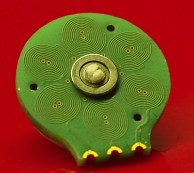
There are two main parts of an electric motor; the stator is stationary while the rotor spins on bearings. Electromagnetic forces are used to cause that spinning action. In this case, Carl has built the electromagnets as coils on a 4-layer circuit board (six coils on each layer). When electrified, a magnetic field is generated that pushes against the rare-earth magnets housed in the rotor.

A couple of things are really interesting here. First, those coils are usually made of “magnet wire” (enamel covered wire that is very thin) wrapped around an iron core. Using the circuit board instead saves both physical space, and the time and expense of wrapping coils of wire in the traditional way. Second, Carl has been designing with manufacture in mind; you can see in the image show that his motor design is dead-simple to assemble by inserting a 3mm bearing in the PCB, inserting magnets into the plastic rotor and snapping it into place. The end goal is to make robot actuators that are part of the circuit board itself.

The genesis of this idea came from Carl’s interest in drone design, in fact, he jumped right into a drone startup immediately after finishing his EE. The company didn’t last, but his thirst for interesting designs is ongoing. When looking at reducing the total parts necessary to build a quadcopter he happened on the idea of PCB-based coils and he’s followed it to this motor design, and beyond to some very interesting flexible-PCB robot design work which you can check out on his Hackaday.io page, YouTube, and Twitter.

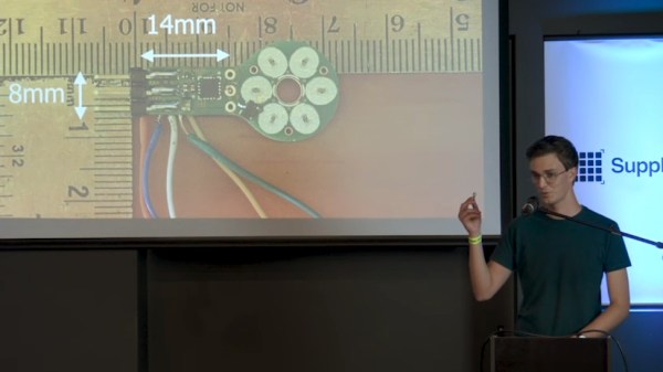
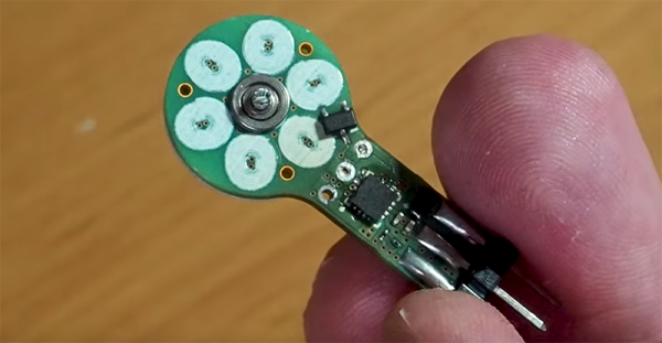
There are of course some trade-offs to this. The motor is low torque since it uses an air core and not an iron core. And he’s had trouble implementing a sensor-less Electronic Speed Controller (ESC) as the back-EMF from the coils appears to be too weak. Not to fret, he added a hall sensor and has succeeded in designing an ESC that measures just 14mm by 8mm. In fact, he’s holding up the ESC and motor in the image at the top of this article!

Continue reading “Designing Tiny Motors Right Into The Robot’s Circuit Board”

Putting A Motor Inside A Speed Controller

One of the more interesting hacks we’ve seen this year is [Carl]’s experimentations with making motors out of PCBs. Honestly, it’s surprising no one has done this before — a brushless motor is just some coils of wire and a few magnets; anyone can turn some coils into traces and make a 3D print that will hold a few magnets. This latest advancement is something else entirely. It’s a motor and an electronic speed controller all in one.

This project is a continuation of [Carl]’s PCB motor project, which started with him routing coils for a brushless motor as traces in a circuit board. Previously, we’ve seen [Carl]’s motor spinning on its own with the help of a small hobby ESC / motor controller meant for model planes and drones. This time, we’ve got something different. It’s an entire controller and motor, integrated into one single PCB.

This is a very, very small motor and ESC combo. The motor driver is a 3x3mm QFN package, and most of the other components are 0201. The main parts are a very tiny triple half-bridge motor driver and a PIC16F microcontroller. This PIC reads a hall sensor to detect the speed of the motor, and with just three pins — power, ground, and a PWM pin — this motor can spin at a set speed.

The future goals of this project are to make it work just like any other hobby ESC — just plug it into a servo controller and let ‘er rip. Since this motor with an integrated PCB requires only three connections, we’re looking at a great tool to add motion and rotation to any project. It’s fantastic, and we can’t wait to see something like this in robots, toys, and other home goods.

Continue reading “Putting A Motor Inside A Speed Controller”