If you play with high speed design for long enough, eventually you’re going to run into clock skew and other weird effects. [Robert Feranec] recently ran into this problem and found an interesting solution to visualizing electric fields in a PCB.
A word of warning before we dig into this, for most of the projects we see on Hackaday something like this is completely superfluous. There aren’t many people dealing with high speed interfaces here, and there aren’t many people dealing with 100 Gigabit per second data links, period. That said, it’s not unheard of, and at the very least it’s interesting to look at.
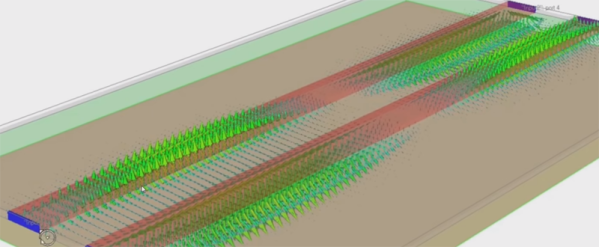
The basics of this video is simulating the signals visually in a differential pair on a (virtual) printed circuit board. The software for this is Simbeor, and [Robert] talked to the founder of the company behind this software after watching a video on simulating electric fields in differential traces. This software does what it says, and is a great illustration of why differential pairs must have the same length.
While this might not be for everyone, it is a fantastic visualization of signals in high-speed design that goes above and beyond what you would expect from a Spice simulation. Even if you’re not doing high-speed design, you may someday and it’s never too soon to get an intuitive understanding of how electrons work.