A Tesla Coil From PCBs

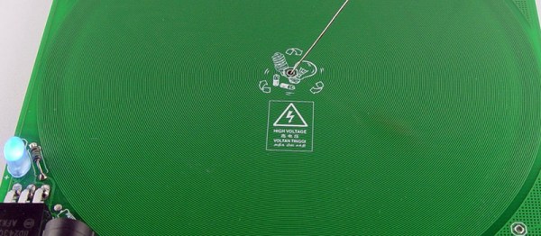
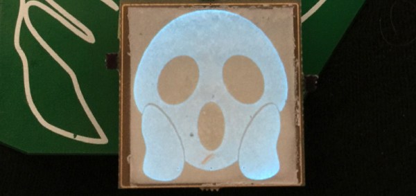
While at the Hacker Hotel camp in the Netherlands back in February, our attention was diverted to an unusual project. [Niklas Fauth] had bought along a Tesla coil, but it was no ordinary Tesla coil. Instead of the usual tall coil and doughnut-shaped capacity hat it took the form of a stack of PCBs with spacers between them, and because Tesla coils are simply cooler that way, he had it playing music as an impromptu MIDI-driven plasma-ball lousdpeaker. Now he’s been able to write up the project we can take a closer look, and it makes for a fascinating intro not only to double-resonant Tesla coils but also to Galium Nitride transistors.

The limiting factor on Tesla coils comes from the abilities of a transistor to efficiently switch at higher frequencies. Few designs make it above the tens of kHz switching frequencies, and thus they rely on the large coils we’re used to. A PCB coil can not practically have enough inductance for these lower frequencies, thus Niklas’ design employs a very high frequency indeed for a Tesla coil design, 2.6 MHz with both primary and secondary coils being resonant. His write-up sets out in detail the shortcomings of conventional MOSFETS and bipolar transistors in this application, and sets out his design choices in using the GaN FETs. The device he’s using is the TI LMG5200 GaN half-bridge driver, that includes all the necessary circuitry to produce the GaN FET’s demanding drive requirements.

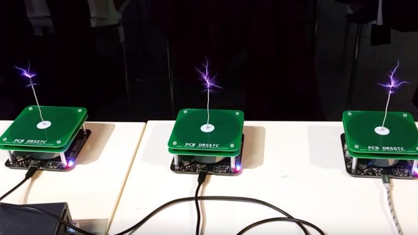
The design files can be found in a GitHub repository, and you can see a chorus of three of them in action in the video below. Meanwhile [Niklas] is a prolific hardware hacker whose work has appeared on these pages in the past, so take a look at his ultrasonic phased array and his x-ray image sensor work.

Continue reading “A Tesla Coil From PCBs”

KiCad And FreeCAD Hack Chat

Join us Wednesday at noon Pacific time for the KiCad and FreeCAD Hack Chat led by Anool Mahidharia!

The inaugural KiCon conference is kicking off this Friday in Chicago, and KiCad aficionados from all over the world are gathering to discuss anything and everything about the cross-platform, open-source electronic design automation platform. As you’d expect, Hackaday will have a presence at the conference, including a meet and greet after party. There’ll also be talks by a couple of our writers, including Anool Mahidharia, who’ll be taking time out of his trip to the States to drop by the Hack Chat with a preview of his talk, entitled “Fast 3D Model Creation with FreeCAD”.

Join us for the KiCad and FreeCAD Hack Chat this week with your questions about KiCad and FreeCAD. If you’ve got some expertise with electronic design tools, make sure you come by and contribute to the discussion too — we’d love to hear your insights. And as always, you can get your questions queued up by leaving a comment on the KiCad and FreeCAD Hack Chat event page and we’ll put them on the list for the Hack Chat discussion.

join-hack-chatOur Hack Chats are live community events in the Hackaday.io Hack Chat group messaging. This week we’ll be sitting down on Wednesday, April 24, at noon, Pacific time. If time zones have got you down, we have a handy time zone converter.

Click that speech bubble to the right, and you’ll be taken directly to the Hack Chat group on Hackaday.io. You don’t have to wait until Wednesday; join whenever you want and you can see what the community is talking about.

Byte Sized Pieces Help The KiCad Go Down

It’s no surprise that we here at Hackaday are big fans of Fritzing KiCad. But to a beginner (or a seasoned veteran!) the learning curve can be cliff-like in its severity. In 2016 we published a piece linking to project by friend-of-the-Hackaday [Chris Gammell] called Contextual Electronics, his project to produce formalized KiCad training. Since then the premier “Getting to Blinky” video series has become an easy recommendation for anyone looking to get started with Libre EDA. After a bit of a hiatus [Chris] is back with bite sized videos exploring every corner of the KiCad-o-verse.

A Happy [Chris] comes free with every video
The original Getting to Blinky series is a set of 10 videos up to 30 minutes long that walks through everything from setting up the the KiCad interface through soldering together some perfect purple PCBs. They’re exhaustive in coverage and a great learning resource, but it’s mentally and logistically difficult to sit down and watch hours of content. Lately [Chris] has taken a new tack by producing shorter 5 to 10 minute snapshots of individual KiCad features and capabilities. We’ve enjoyed the ensuing wave of learning in our Youtube recommendations ever since!

Selecting traces to rip up

Some of the videos seem simple but are extremely useful. Like this one on finding those final disconnected connections in the ratsnest. Not quite coverage of a major new feature, but a topic near and dear to any layout engineer’s heart. Here’s another great tip about pulling reference images into your schematics to make life easier. A fantastic wrapped up in a tidy three minute video. How many ways do you think you can move parts and measure distances in the layout editor? Chris covers a bunch we hadn’t seen before, even after years using KiCad! We learned just as much in his coverage of how to rip up routed tracks. You get the idea.

We could summarize the Youtube channel, but we aren’t paid by the character. Head on down to the channel and find something to learn. Make sure to send [Chris] tips on content you want him to produce!

Here’s A Tesla Coil You Can Wear

It’s badgelife season, and if you need an idea for a killer piece of wearable electronics, look no further than this PCB Tesla coil. Yes, it’s killer, doubly so if you’re wearing a pacemaker.

This project was inspired by an earlier Tesla coil on a PCB project that used 160 turns of 6 mil traces on a circuit board as the secondary. All the electronics are there, and it’s powered by USB. Plug this thing in, and you have a pocket full of lightning that’s approximately 30kV. It probably won’t kill you if you touch it, but let’s not test that too much. [Bobricious] took this idea and ran with it, stripping the circuit down to its bare minimum. Now it’s just a single transistor, with all the other parts printed on a circuit board.

There is one problem with making a Tesla Coil on a PCB, and that’s the number of turns on the coil. Any Tesla coil you’ll find is really just the clever application of a single thin wire wrapped around itself a few hundred or thousands of times. This Tesla coil is no different, and in this case it’s 240 turns of a single trace wrapping around a PCB that is 150mm square. [Bobricius] is one of the kings of putting tiny coils on a PCB, and his fiberglass brushless motor is a testament to that. We also just covered his circular linear motor raceway which also uses PCB coils.

The circuit is simple, just a power jack that accepts something around 20 Volts, a single BD243 transistor, an LED, and an 82k resistor. With that, you can lay a small neon tube on the PCB and watch it light up. With another PCB and another neon tube, this circuit board can transfer wireless power. It’s a fun toy, and it’s all PCB tech.

Add-Ons Go Electroluminescent

It’s that time of the year again, and once more we’re faced with the latest innovations in Badgelife, the movement to explore the artistic merits of electronics and manufacturing. This is an electroluminescent printed circuit board, and it’s some of the finest work we’ve seen. It’s also a Shitty Add-On that glows blue.

The process for applying an electroluminescent coating to printed circuit boards is, surprisingly, something we’ve covered before. Late last year, [Ben Krasnow] delved deep into a DIY EL display. The process is expensive, but all the products come from a company called Lumilor. The first step in this process is applying a thin conductive coating on a substrate with an airbrush. Since the entire idea of printed circuit boards is to have a layer of conductive material etched into any shape you want, the simple circuit board is the idea experimental platform for playing with EL displays. Traditionally, EL displays were made entirely with a silk screen process, like [Fran]’s ongoing attempt to recreate the Apollo DSKY display.

The electronics for this badge are simply a Microchip MIC4832 EL Driver, which converts the 3.something volts from the add-on header into 100 or so Volts AC at hundreds of Hz. This is a single-chip solution to driving EL displays, and the only other parts you need are an inductor, diode, and a few caps and resistors. An ATtiny85 can be used to blink the circuits, or, alternatively, you could copy [Ben]’s work and build a character EL display.

The process of applying an electroluminescent coating to a PCB does require a spray gun or airbrush, and the chemicals are a bit expensive. This, though, is pushing the boundaries of what can be done with artistic PCBs. It’s new applications of technology, simply as wearable electronics. It’s the best example of the possibilities of the medium and some of the best work that’s come out of the Badgelife scene.

These Wire Strippers Are Made From PCBs

The rise in cheap PCB fabrication has made old-school prototyping methods such as wire wrapping somewhat passé, but it still has its place. And if you’re going to wire wrap, you’re going to want a quick and easy way to strip that fine Kynar-insulated wire. So why not use PCB material to make this handy wire-wrapping wire stripper?

The tool that [danielrp] built is pretty simple – just a pair of razor blades held together so as to form a narrow slot to cut insulation while leaving the conductor untouched. The body of the tool is formed of two PCBs, between which the blades are sandwiched. [danielrp] designed the outline of the PCBs in DraftSight, then exported a DXF into EAGLE to make the Gerbers. The fabricated boards needed a little post-processing, including tapping the holes on one side to accept the screws that hold the tool together. We were surprised that FR4 took the threads at all, but it seems to work for this low-torque application. The disposable snap-type blades were sandwiched between the PCBs and the gap between them adjusted for nick-free stripping. The video below shows the design and build process.

We always appreciate homemade tools, and the fact that you can get a stack of PCBs for almost nothing makes us wonder what else we could use them for. We recently saw them used in a unique word clock, and even turned into a folding circuit sculpture.

Continue reading “These Wire Strippers Are Made From PCBs”

Hackaday Links Column Banner

Hackaday Links: April 7, 2019

It’s April, which means all the people responsible for doubling the number of badges at DEF CON are hard at work getting their prototypes ready and trying to fund the entire thing. The first one out of the gate is Da Bomb, by [netik] and his crew. This is the same team that brought you the Ides of DEF CON badge, a blinky wearable multiplayer game that’s SPQR AF. Da Bomb is now a Kickstarter campaign to get the funding for the run of 500, and you’re getting a wearable badge filled with puzzles, Easter eggs, and a radio-based sea battle game that obviously can’t be called Battleship, because the navy doesn’t have battleships anymore.

Speaking of badges and various badge paraphernalia, there’s a new standard for add-ons this year. The Shitty Add-On V.1.69bis standard adds two pins and a very secure shrouded connector that solves all the problems of last year’s standard. [AND!XOR] just released a Shitty Brooch that powers all Shitty Add-Ons with a CR2032 battery. All the files are up on the Gits, so have fun.

You can 3D print anything if you don’t mind dealing with supports. But how to remove supports? For that [CCecil] has a great tip: use Chap stick. This is a print that used supports and it’s perfectly clean, right off the bed. By inserting a suspend (M600) command at the z-height of the top of the interface layer, then adding Chap stick on the top layer, everything comes off clean. Neat.

Speaking of 3D printing, here’s a project for anyone with the patience to do some serious modeling. It’s a pocket Soviet record player, although I think it’s more properly called a gramophone. It’s crank powered, so there’s a spring in there somewhere, and it’s entirely acoustic with zero electronics. Yes, you’re going to need a needle, but I’d be very interested in seeing somebody remake this using modern tools and construction materials.