Modifying A Printer For PCB Fabbing

ohgodmyeyes

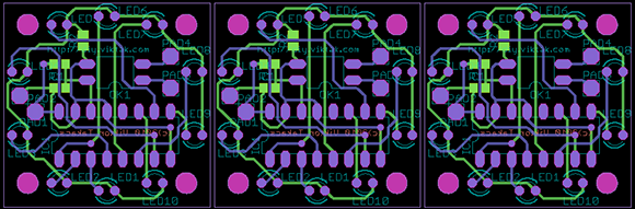
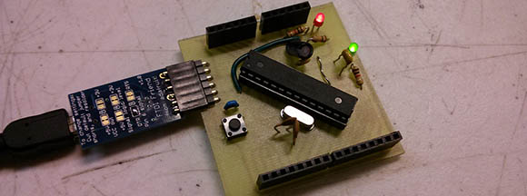
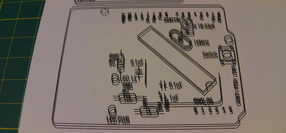
The migraine-inducing image above is the product of [Rupert Hirst]’s attempts at home PCB fabrication. He’s using the toner transfer method – printing a circuit on a piece of transparency sheet with a laser printer, setting it on a piece of copper clad board, and sending the whole assembly through a laminator. It’s a fairly straightforward process, but if you can’t run a transparency sheet through a printer multiple times your etch resist won’t hold up too well. Of course the transparency sheet must be aligned each time it goes through the printer, so [Rupert] came up with a modification that ensures laser toner goes only where it’s supposed to.

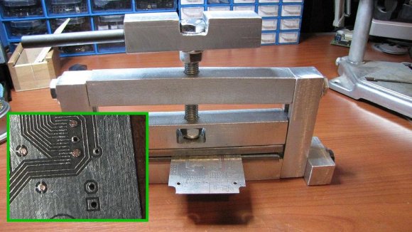
[Rupert] picked up a Samsung ML-2165W laser printer for his PCB fab shop, but printing the same image multiple times on the same transparency sheet would result in unusable masks. This problem was fixed with a few plastic shims used to hang door frames and a card stock tray that ensures the transparency sheet goes through the printer the same way every time.

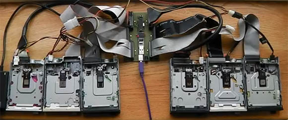
We saw [Rupert]’s homebrew PCB fabrication process a few weeks ago when he sent in his six channel floppy drive MIDI synth. In his build video, [Rupert] demonstrated what is possibly the cleanest toner transfer PCB we’ve seen to date. You can check out his etching process in the video after the break.

Continue reading “Modifying A Printer For PCB Fabbing”

Panelizing PCBs In Eagle

final_panel

A lot of the board houses out there including Seeed and ITead studios have a fixed size for circuit boards before the price goes up. A one-inch square board costs the same as a much larger 5cm x 5cm board, making panelized PCBs a great way to get more boards for the same amount of money. Trying to panelize a board in Eagle with copy and paste is a chore without the right tools, though, so we’re happy to see a great panelization tutorial from [Victor].

To panelize one of his boards for a PCB order, [Victor] used one of Eagle’s User Language Programs to duplicate the part names on the additional boards. After that, it was a simple matter of running a CAM job to generate the necessary Gerber files.

Of course once the boards arrive, you’ll have to cut them apart from each other. This can be done with everything from a Dremel to a hack saw to a metal shear, but we’re wondering what other Hackaday readers are using to cut up PCBs. Leave a note in the comments with your preferred method of depanelization.

Making Eagle Work With Circuits.io

IO

Ever so slowly, we’re inching towards a world of Internet-based electronic design tools. The state of these tools, including Upverter and other cloud-based solutions, hasn’t been all that great until now; with any new piece of schematic capture and PCB layout software, the libraries will be woefully inadequate in the beginning. This is about to change, because circuits.io is now allowing Eagle libraries to be imported.

As you may well be aware, Eagle is the de facto standard for homebrew and hobbyist schematic capture and board layout software. Even though Eagle isn’t open source and is limited to rather small PCBs with the free version, somehow Eagle has retained its popularity, most likely due to the huge number of component libraries available.

By allowing users and designers to import Eagle libraries, the folks at circuits.io are capitalizing on a huge amount of work done by designers and engineers over the years in creating custom Eagle parts for just about every component imaginable. It’s a great accomplishment for the circuits.io team and a boon for anyone wanting to move their PCB design tools over to the cloud.

Via Press Crushes Copper To Make A Mechanical Connection

via-press-in-action

[Jay] was looking for a way to make his own vias on homemade double-sided PCBs when he stumbled across this post from about five years ago. The technique shown here makes mechanical vias and was developed by [Retromaster]. There’s no soldering involved, instead he uses some solid core copper wire and a press to crush it tightly against the board.

The press is made from aluminum stock, with a couple of plates of stainless steel which come in contact with the board. The aluminum stock is easy to work with, but it’s relatively soft which is the reason for the addition of steel. He uses copper wire which already fits tightly in the hole through the substrate. After clipping off the excess as near to the board as possible a trip through the press leaves each side flat as shown in the inset image.

We looked through some of the other projects we’ve seen from [Retromaster] like the Atari 2600 in an FPGA and this emulated Amiga floppy drive. But we didn’t see any diy boards where he used this crushing technique.

Building A Six-channel Floppy Drive Synth From Start To Finish

floppy

We’ve seen scores of floppy drives play music, but never before have we seen a project as clean as [Rupert]’s Moppyduino. It’s an Arduino-based board that controls the stepper motors in six separate floppy drives, coaxing them in to playing music from a MIDI file.

The Moppyduino is more than just a convenient way to control the stepper motors in six floppy drives. It’s also a great example of what can be done with home PCB fabrication; the entire project was designed and constructed in [Rupert]’s workshop.

After designing the circuit, [Rupert] printed it out on a laser printer onto a plastic transparency sheet. This was transferred over to a copper clad board, etched, and drilled. After assembly, [Rupert] attached a USB FTDI controller to receive data converted from MIDI data with a Java app.

The end result – housed in a custom Corian enclosure – is one of the best looking floppy drive synths we’ve ever seen. You can check out the process of building this awesome instrument after the break.

Continue reading “Building A Six-channel Floppy Drive Synth From Start To Finish”

Script Lets You Import Eagle Boards For Use In FreeCAD

eagle-designs-imported-for-freecad

[Christian Aurich] wanted to use his Eagle CAD circuit board design in a proper CAD program in order to design enclosures. There are already a few options along these lines, but they didn’t quite fit his needs so he developed a script to import Eagle boards into FreeCAD. The script is packaged as a python macro for FreeCAD.

In describing the shortcomings of what’s already out there [Christian] does mention the use of EagleUp to model boards in Google SketchUp. But he feels the way the data is produced by SketchUp makes these models work well with 3D printing, but says they’re not easy to use with mechanical design CAD software. He also feels that the photo-realistic renderings are useless when developing enclosures.

It’s worth mentioning that this approach is only possible because CadSoft’s migration to XML makes it dead simple to get at the data.

PCB Production Workshop Means Everyone Gets An Arduino

nano

Over at the LVL1 hackerspace in Lousiville, [Brad] is putting together a workshop on etching PCBs at home. [Brad] wanted all the participants to take home something cool, so he settled on an Arduino clone as the workshop’s project.

The clone [Brad] used is the Nanino, a single-sided board we’ve seen before. Unfortunately, there aren’t any CAD files for the Nanino and doing a toner transfer with the existing PDFs was a pain. This led [Brad] to redraw the Nanino in Diptrace and put the files up for everyone to grab.

In his workshop, [Brad] is going to be using a laser printer, hydrogen peroxide, and HCl. one of the most common setups for home etching. If you’re in the Louisville area, you can make your own Nanino with a home etching workshop on March 16th. Be careful, though: those LVL1 guys are pretty weird; they have a moat and are building a homicidal AI.