[Roo] was tasked with finding a better way to take corporate employee photos. The standard method was for a human resources employee to use a point and shoot camera to take a photo of the new recruits. The problem with this method is many people feel awkward trying to force a smile in front of other people. Plus, if the photo turns out poorly many people won’t ask to have it retaken so as not to feel vain or inconvenience the photographer. [Roo’s] Raspberry Pi powered photo booth solves this problem in a novel way.
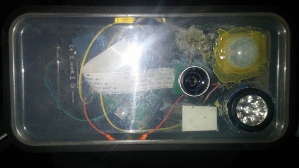
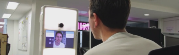
The new system has the employee use their own mobile phone to connect to a website running on the Pi. When the employee tells the Pi to snap a photo, the system uses the Raspberry Pi camera module to capture an image. [Roo] actually 3D printed a custom adapter allowing him to replace the standard camera lens if desired. The photo can be displayed on an LCD screen so the user can re-take the photo if they wish.
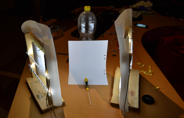
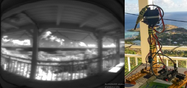
The system is built into a custom case made from both 3D printed and laser cut parts. The front plate is a frosted white color. [Roo] placed bright white lights behind the front panel in order to act as a flash. The frosted plastic diffuses the light just enough to provide a soft white light for each photo taken. Once the photo is selected, it can then be uploaded to the company database for use with emails, badges, or whatever else.
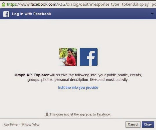
[Roo] also mentions that the system can easily be changed to send photos via Twitter or other web applications. With that in mind, this system could be a great addition to any hackerspace or event. The code for an older version of the project can be found on the project’s github page.
Continue reading “Smile For The Raspberry Pi Powered Photo Booth”
 A master key for the NYC Subway was compromised and available for sale.
 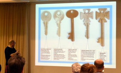 Worse, was the availability of fire-department
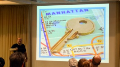
  [Jos’] example of doing the right thing is to use a “prop” key for news stories. Here he is posing with a key after the talk. Unfortunately this is my own house key, but I’m the one taking pictures and I have blurred the teeth for my own security. However, I was shocked during image editing at the quality of the outline in the image — taken at 6000×4000 with no intent to make something that would serve as a source for a copy. It still came out remarkably clear.