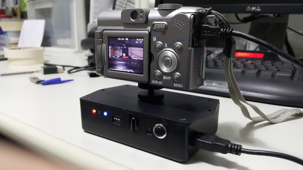
[Nightflyer] has been working on an open source project he calls CAMdrive. CAMdrive is designed to be a multi-axis controller for time-lapse photography. It currently only supports a single axis, but he’s looking for help in order to expand the functionality.
You may already be familiar with the idea of time-lapse photography. The principal is that your camera takes a photo automatically at a set interval. An example may be once per minute. This can be a good way to get see gradual changes over a long period of time. While this is interesting in itself, time-lapse videos can often be made more interesting by having the camera move slightly each time a photo is taken. CAMdrive aims to aid in this process by providing a framework for building systems that can pan, tilt, and slide all automatically.
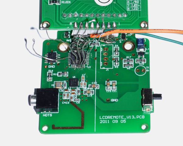
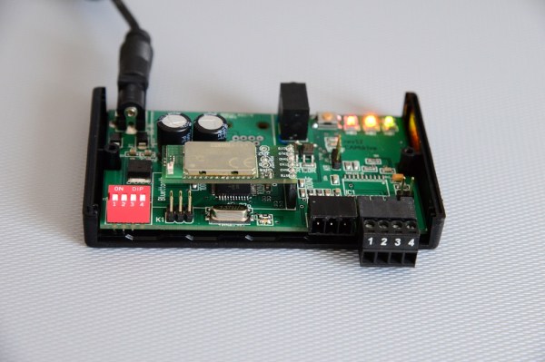
The system is broken out into separate nodes. All nodes can communicate with each other via a communication bus. Power is also distributed to each node along the bus, making wiring easier. The entire network can be controlled via Bluetooth as long as any one of the nodes on the bus include a Bluetooth module. Each node also includes a motor controller and corresponding motor. This can either be a stepper motor or DC motor.
The system can be controlled using an Android app. [Nightflyer’s] main limitation at the moment is with the app. He doesn’t have much experience programming apps for Android and he’s looking for help to push the project forward. It seems like a promising project for those photography geeks out there. Continue reading “CAMdrive Is An Open Source Time-lapse Photography Controller”