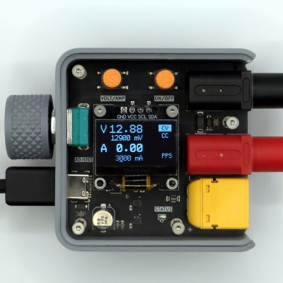
USB-C For Hackers: Program Your Own PSU

Last time, I showed off a few ways you can convert an existing PSU to USB-C duty, and zoomed in on a particular way you can use to convert one of the ever-abundant 18 V – 20 V laptop PSUs to USB-C. All we have left is to write software for it, and I’ll explain how it works. There’s also that one cool USB-C secret I’ve found out, but you’ll have to read on to find out more.

From the last article, we have a board that has an RP2040 and FUSB302 combo on it, which takes a 20 V DC PSU input from a laptop brick, and can switch either 5 V, 20 V or 0 V to its USB-C socket using FETs. The USB-C communication firmware is simple enough, but there’s caveats, especially regarding safety. Let’s go through those!

The Code Logic

VBUS has to be non-powered by default – we only supply 5 V when the FUSB302 detects a 5.1 kΩ pulldown on one of the CC lines. After supplying 5 V, we send out PSU capability advertisements, of the kind that we’ve learned to parse in the Replying PD article – and whenever we get a Request, we have to switch to the requested profile, connecting the voltage rail requested to the FET. I opt to not do any current consumption control in this design, assuming a well-behaved device, but you theoretically should do that. It wouldn’t be hard to add a high-side current sensor, say, something from Analog Devices – I just don’t want to do that now, especially given that I’m already using two of the exposed ADC pins to do Lenovo/HP PSU capability detection instead, one is used up for VBUS measurement, and the fourth is used for VIN (20 V rail) measurement – that’s four ADCs, which is as much as the RP2040 has got. However, if I ever need more ADCs, I can add an analog mux like 4051 in the next version! Continue reading “USB-C For Hackers: Program Your Own PSU”

A Nicer Controller For Cheap Power Supply Modules

These days, you can get all kinds of cheap power supply modules off a variety of online vendors. A lot of examples from brands like Juntek and Drok often have pretty poor interfaces though, with a couple of tactile buttons and a simple 7-segment display. [rin67630] decided to whip up a better controller with a much more informative display.

The controller is designed to work with programmable buck converter modules like the DPS3806, Buck3603, and BST900. It’s based on a TTGO ESP32 with an integrated color TFT LCD. It displays voltage at the input and output, the same for current, along with current setpoints. It also allows for control of a fan and charge cycles if so desired, and it has the ability to fetch time from an NTP server for proper scheduling.  There’s also a web interface complete with graphs for really diving down into the nitty-gritty. Future plans include adding an MPPT solar charging capability.

If you’ve ever wanted a cheap power supply module with really low-level control and rich data display, this could be just what you need. Meanwhile, you’ve got your own neat power supply in the works, don’t hesitate to drop us a line. 

USB-C For Hackers: Build Your Own PSU

What if you wanted to build your own USB-C PSU? Good news – it’s easy enough! If you ever wanted to retrofit a decent DC PSU of yours to the USB-C standard, say, you got a Lenovo/HP/Dell 19V-20V charger brick and you’ve ever wished it were USB-C, today is the day when we do exactly that. To be fair, we will cheat a bit – but only a tiny bit, we won’t be deviating too much from the specification! And, to begin with, I’ll show you some exceptionally easy ways that you can turn your DC PSU into a USB-C compatible one, with a simple module or a few.

Turning a 20 V PSU into a USB-C PSU feels natural if you want to charge a laptop – those tend to request 20 V from a USB-C PSU anyway, so what’s the big deal? However, you can’t just put 20 V onto a USB-C connector – you have to add a fair bit of extra logic to make your newly christened USB-C PSU safe to use with 5 V devices, and this logic also requires you go through a few extra steps before 20 V appears on VBUS. Any USB-C PSU has to output 5 V first and foremost whenever a device is connected, up until a higher voltage is negotiated digitally, and the PSU may only switch to a higher voltage output when it’s requested to do so.

Now, for that, a PSU offers a list of profiles, and we looked into those profiles in the Replying PD article – each profile is four bytes that contain information about the profile voltage, maximum current that the device may draw at that voltage, and a few other details. For a PSU to be USB-C compliant, the USB-C specification says that, in addition to 5 V, you may also offer 9 V, 15 V, and 20 V.

Also, the specification says that if a PSU supports certain in-spec voltage like 15 V, it’s also required by the spec to offer all of the spec-defined voltages below the maximum one – for 15 V, that also requires supporting 9 V. Both of these are UX requirements, as opposed to technical requirements – it’s easier for device and PSU manufacturers to work with a small set of pre-defined voltages that majority of the chargers will support, but in reality, you can actually offer any voltage you want in the PSU advertisement; at worst, a device is going to refuse and contend with slowly charging from the 5 V output that you’re required to produce.

I’d like to walk you through how off-the-shelf USB-C PSUs work, all of the options you can use to to create one, and then, let’s build our own USB-C PSU from scratch! Continue reading “USB-C For Hackers: Build Your Own PSU”

Power Supplies Without Transformers

For one-off projects or prototyping, it’s not too hard to find a wall wart or power supply to send a few joules of energy from the wall outlet to your circuit. Most of these power supplies use a transformer to step down the voltage to a more usable level and also to provide some galvanic isolation to the low voltage circuit. But for circuits where weight, volume, or cost are a major concern, a transformer may be omitted in the circuit design in favor of some sort of transformerless power supply.

While power supplies with this design do have many advantages, some care needs to be taken with regard to safety. The guide outlines four designs of increasing complexity which first puts out a basic transformerless power supply, using a series capacitor to limit current. To bring the voltage to an acceptable level, a recognizable bridge rectifier is paired with a capacitor as well as a zener diode. The second circuit presented adds voltage stabilization using a transistor and 78XX regulator. From there, zero-crossing detection is added to limit inrush surge currents, and the final design uses the venerable 555 timer to build a switching power supply.

Although it is noted several times throughout the guide, we’ll still point out here that transformerless designs like these introduce several safety issues since a mistake or fault can lead to the circuit being exposed to the mains voltage. However, with proper care and design it’s possible to make use of these designs to build more effective power supplies that can be safe to use for powering whatever circuit might energy but might not require the cost or weight of a transformer. For more on the theory of these interesting circuits and a few examples of where they are often found, check out the shocking truth about transformerless power supplies.

Thanks to [Stephen] for the tip!

Buck Converter Takes 8V To 100V

For those living before the invention of the transistor, the modern world must appear almost magical. Computers are everywhere now and are much more reliable, but there are other less obvious changes as well. Someone from that time would have needed a huge clunky machine like a motor-generator set to convert DC voltages, but we can do it with ease using a few integrated circuits. This one can take a huge range of input voltages to output a constant 5V.

The buck converter was designed by [hesam.moshiri] using a MP9486 chip. While it is possible to use a multipurpose microcontroller like something from Atmel to perform the switching operation needed for DC-DC converters, using a purpose-built chip saves a lot of headache. The circuit was modified a little bit to support the higher input voltage ranges and improve its stability and reliability. The board is assembled in an incredibly tiny package with inputs and outputs readily accessible, so it would be fairly simple to add one into a project rather than designing it from scratch.

Even though buck converters, and other DC converters like boost and the mysterious buck-boost converter, seem like magic even to us, there is some interesting electrical theory going on if you’re willing to dive into the inner workings of high-frequency switching. Take a look at this explanation we featured a while back to see more about how buck converters, the more easily understood among them, work.

AC-DC Converter Is Reliable, Safe, And Efficient

When first starting an electronics project, it’s not uncommon to dive right in to getting the core parts of the project working. Breadboarding the project usually involves working with a benchtop power supply of some sort, but when it comes to finalizing the project the actual power supply is often glossed over. It’s not a glamorous part of a project or the part most of us want to be working with, but it’s critical to making sure projects don’t turn up with mysterious issues in the future. We can look to some others’ work to simplify this part of our projects, though, like this power supply from [hesam.moshiri].

The power supply is designed around a switch-mode topology known as a flyback converter. Flyback converters work by storing electrical energy in the magnetic field of a transformer when it is switched on, and then delivering that energy to the circuit when it is switched off. By manipulating the switching frequency and turns ratios of the transformer, the circuit can have an arbitrary output voltage. In this case, it is designed to take 220V AC and convert it to 8V DC. It uses a simplified controller chip to decrease complexity and parts count, maintains galvanic isolation for safety, and is built to be as stable as possible within its 24W power limitation to eliminate any potential issues downstream.

For anyone trying to track down electrical gremlins in a project, it’s not a bad idea to take a long look at the power supply first. Any noise or unwanted behavior here is likely to cause effects especially in projects involving sensors, ADC or DAC, or other low-voltage or sensitive components. The schematic and bill of materials are available for this one as well, so anyone’s next project could use this and even make slight adjustments to change the output voltage if needed. And, if this is your first introduction to switched-mode power supplies, check out this in-depth look at the similar buck converter circuit to better understand what’s going on behind the scenes on these devices.

Continue reading “AC-DC Converter Is Reliable, Safe, And Efficient”

Tearing Down And Improving A Professional Power Supply

[OZ2CPU] has an HP power supply that is about 30 years old. It looks brand new, though, and has three outputs and includes tracking for the adjustable positive and negative supply. After a quick demo of the unit’s features, he tears it all down so we can see inside. You can catch the video below.

Some similar supplies offer a 10-turn adjustment knob, but this one doesn’t. Inside is a beefy transformer and quite a few through-hole components. There was room to change the main adjusted pot to a 10-turn unit, so he made the mod.

Continue reading “Tearing Down And Improving A Professional Power Supply”