Retrotechtacular: Hallicrafters Goes To War

When the USA entered World War Two, they lacked a powerful mobile communications unit. To plug this gap they engaged Hallicrafters, prewar manufacturers of amateur radio transmitters and receivers, who adapted and ruggedized one of their existing products for the application.

The resulting transmitter was something of a success, with production running into many thousands of units. Hallicrafters were justifiably proud of it, so commissioned a short two-part film on its development which is the subject of this article.

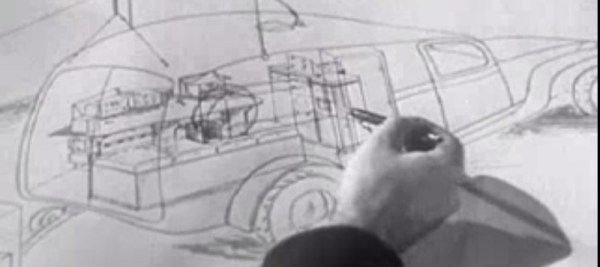
The transmitter itself was a very high quality device for the era, but even with the film’s brief insight into operating back in the AM era the radio aspect is not what should capture your interest. Instead of the radio it is the in-depth tour of an electronics manufacturing plant in the war years that makes this film, from the development process of a military product from a civilian one through all the stages of production to the units finally being fitted to Chevrolet K-51 panel vans and shipped to the front. Chassis-based electronics requiring electric hoists to move from bench to bench are a world away from today’s surface-mount micro-circuitry.

So sit back and enjoy the film, both parts are below the break.

Continue reading “Retrotechtacular: Hallicrafters Goes To War”

RF Biscuit Is A Versatile Filter Prototyping Board

As anyone who is a veteran of many RF projects will tell you, long component leads can be your undoing. Extra stray capacitances, inductances, and couplings can change the properties of your design to the point at which it becomes unfit for purpose, and something of a black art has evolved in the skill of reducing these effects.

RF Biscuit is [Georg Ottinger]’s attempt to simplify some of the challenges facing the RF hacker. It’s a small PCB with a set of footprints that can be used to make a wide range of surface-mount filters, attenuators, dummy loads, and other RF networks with a minimum of stray effects. Provision has been made for a screening can, and the board uses edge-launched SMA connectors. So far he’s demonstrated it with a bandpass filter and a dummy load, but he suggests it should also be suitable for amplifiers using RF gain blocks.

Best of all, the board is open source hardware, and as well as his project blog he’s made the KiCad files available on GitHub for everyone.

It’s a tough challenge, to produce a universal board for multiple projects with very demanding layout requirements such as those you’d find in the RF field. We’re anxious to see whether the results back up the promise, and whether the idea catches on.

This appears to be the first RF network prototyping board we’ve featured here at Hackaday. We’ve featured crystal filters before, and dummy loads though, but nothing that brings them all together. What would you build on your RF Biscuit?

Michael Ossmann Makes You An RF Design Hero

To a lot of people, radio-frequency (RF) design is black magic. Even if you’ve built a number of RF projects, and worked your way through the low-lying gotchas, you’ve probably still got a healthy respect for the gremlins lying in wait around every dimly-lit corner. Well, [Michael Ossmann] gave a super workshop at the Hackaday Superconference to give you a guided tour of the better-illuminated spaces in RF design.

five_rules[Michael] is a hacker-designer, and his insights into RF circuit design are hard-won, by making stuff. The HackRF One is probably his most famous (and complex) project, but he’s also designed and built a number of simpler RF devices. And the main point of his talk is that there’s a large range of interesting projects that are possible without getting yourself into the fringes of RF design (which require expensive test equipment, serious modelling, or a Ph.D. in electro-wavey-things).

You should watch [Mike]’s workshop which is embedded below. That said, here’s the spoilers. [Mike] suggests five rules that’ll keep your RF design on the green, rather than off in the rough.

Continue reading “Michael Ossmann Makes You An RF Design Hero”

Triple Threat RTL-SDR System Reads Trunked Radio

In the old days, if you wanted to listen to police, fire, or other two-way radio users, you didn’t need much more than a simple receiver. Today, you are more likely to need something a little more exotic thanks to the adoption of trunked radio systems. To pick up the control channels and all the threads of a talk group conversation, you might need a wide bandwidth receiver.

[Luke Berndt] found he needed 6 MHz to monitor the stations he wanted to hear. This is easily in the reach of dedicated software defined radios (SDR). However, [Luke] wanted to use cheap RTL-SDRs and their bandwidth is about 2 MHz. The obvious hacker solution? Use three of them!

If you haven’t looked at a trunked system before, it essentially allows a large number of users to share a relatively small number of channels. When someone wants to talk, they move to an unused channel just for that transmission. Suppose Alice asks Bob a question that happens to be on channel 12. Bob’s reply might be on channel 4. A follow up from Alice could be on channel 3.

In practice, this means that receiving the signal isn’t difficult to decode. It is just difficult to find (and follow as it jumps around). This is an excellent job for multiple SDRs and the approach even reduces the burden on the CPU, which doesn’t have to decode signals that aren’t essential to the conversation.

[Luke] includes source code and also notes how to change the serial numbers of the dongles since each has to be unique. We have seen so many great projects with the RTL-SDR that it is hard to choose our favorite. It is especially great knowing that the dongle was only meant to receive television, and all these projects are hacks in the best sense of the word.

Thanks [WA5RRior] for the tip.

A Spicy Regenerative Reciever

We recently posted a three-part series about using LTSpice to simulate electronic circuits (one, two, three). You might have found yourself wondering: Can you really simulate practical designs with the program? This quick analysis of [QRP Gaijin’s] minimalist regenerative receiver says “yes”.

Continue reading “A Spicy Regenerative Reciever”

Google Is Building A 100kW Radio Transmitter At A Spaceport And No One Knows Why

You can find the funniest things in public government documents. There’s always ample evidence your local congress critter is working against the interests of their constituency, nation, and industry controlled by the commission they’re chairperson of. Rarely, though, do you find something surprising, and rarer still does it portend some sort of experiments conducted by Google at a spaceport in New Mexico.

In a publication released last week, Google asked the FCC to treat some information relating to radio experiments as confidential. These experiments involve highly directional and therefore high power transmissions at 2.5 GHz, 5.8GHz, 24GHz, 71-76GHz, and 81-86GHz. These experiments will take place at Spaceport America, a 12,000 foot runway in the middle of New Mexico occasionally used by SpaceX, Virgin Galactic, and now Google.

For the most part, this document only tells the FCC that Google won’t be causing harmful interference in their radio experiments. There few other details, save for what bands and transmitters Google will be using and an experimental radio license call sign (WI9XZE) that doesn’t show up in the FCC database.

Of the few details listed in the documents, one thing does pop out as exceptionally odd: a 70-80 GHz transmitter with an effective radiated power (ERP) 96,411 W. That’s close enough to 100 kilowatts to call it as such. This is the maximum effective radiated power of the highest power FM stations in the US, but radio stations are omnidirectional, whereas Google is using very high gain antennas with a beam width of less than half a degree. The actual power output of this transmitter is a mere half watt.

The best guess for what Google is doing out in the New Mexico desert is Project Skybender, a project to use millimeter waves to bring faster Internet to everyone. There aren’t many details, but there is a lot of speculation ranging from application in low Earth orbit to something with Google Loon.

Retrotechtacular: Transmission Lines

This great old video (embedded below the break) from Tektronix in the mid-60s covers a topic that seems to confuse folks more than it should — transmission lines. We found it on Paul Carbone’s blog, a great site for aficionados of old analog scopes in its own right.

As with many of these older videos, the pacing is a bit slow by today’s standards, but the quality of the material eventually presented more than makes it worth the effort to reign in your ADHD. For a preview, you can skip to the end where they do a review of all the material.

They start off 5:31 with a pulse travelling down a wire pair, and take a very real-world approach to figuring out the characteristic impedance of the line: if the pulse was created by a battery of 9V, how much current is flowing? If the DC resistance of the wire is zero then there should be an infinite current by Ohm’s law, and that’s clearly not happening. This motivates the standard analysis where you break the wire down into distributed inductance and capacitance.

Of course they do the experiment where you inject a pulse into a long loop of coaxial cable and play around with the termination at the other end of the line. They also measure the velocity factor of the line. Our only gripe is that they don’t tap the line in different places to demonstrate standing waves. The good news is that we’ve got YouTube (and [w3aew]) for that.

If you’ve got 23 minutes to spare, and are curious about transmission lines or just enjoy the soothing voice of a trained radio announcer reading out values of various termination resistors, this old gem is just the ticket. Enjoy!

Continue reading “Retrotechtacular: Transmission Lines”