Weather matrix lamp

Pi Weather Lamp Puts Lava Lamps To Shame

Representing the weather on an LED lamp in a manner that’s easy to interpret can be difficult, but [Gosse Adema]’s weather/matrix lamp makes it not only obvious what the weather is but also offers a very attractive display. For rain, drops of light move downward, and for wind, sideways. The temperature is shown using a range of colors from red to blue, and since he is situated in the Netherlands he needed snow, which he shows as white. A rainy, windy day has lights moving both down and sideways with temperature information as the background.

Weather matrix lamp

To implement it he mounted LED strips inside a 3D printed cylinder with reflectors for each LED, all of which fitted into a glass cylinder taken from another lamp purchased online. The brains of it is a Raspberry Pi Zero W housed in the bottom along with a fan. Both the LEDs and the fan are controlled by the Pi. He took a lot of care with power management, first calculating the current that the LEDs would draw, and then writing Python code to limit that draw. However upon measurement, the current draw was much lower than expected and so he resized the power supply appropriately. He also took care to correctly size the wires and properly distribute the power with a specially made power distribution board. Overall, we really like the thorough job he’s done.

But then again, what’s not to like about [Gosse]’s projects. In the area of lighting, he’s dazzled us with WiFi controlled Christmas tree ornaments, but he’s also delighted us with a Prusa i3 based LEGO 3D printer on which he printed LEGO parts and then made a special extruder for printing chocolate.

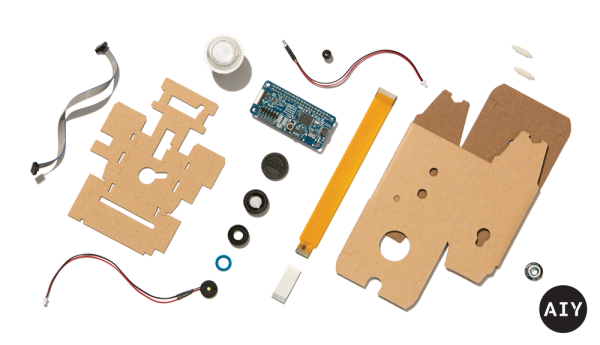
Google's AIY Vision Kit exploded view

Google’s AIY Vision Kit Augments Pi With Vision Processor

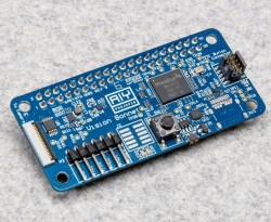
Google has announced their soon to be available Vision Kit, their next easy to assemble Artificial Intelligence Yourself (AIY) product. You’ll have to provide your own Raspberry Pi Zero W but that’s okay since what makes this special is Google’s VisionBonnet board that they do provide, basically a low power neural network accelerator board running TensorFlow.

AIY VisionBonnet with Myriad 2 (MA2450) chip

The VisionBonnet is built around the Intel® Movidius™ Myriad 2 (aka MA2450) vision processing unit (VPU) chip. See the video below for an overview of this chip, but what it allows is the rapid processing of compute-intensive neural networks. We don’t think you’d use it for training the neural nets, just for doing the inference, or in human terms, for making use of the trained neural nets. It may be worth getting the kit for this board alone to use in your own hacks. An alternative is to get Modivius’s Neural Compute Stick, which has the same chip on a USB stick for around $80, not quite double the Vision Kit’s $45 price tag.

The Vision Kit isn’t out yet so we can’t be certain of the details, but based on the hardware it looks like you’ll point the camera at something, press a button and it will speak. We’ve seen this before with this talking object recognizer on a Pi 3 (full disclosure, it was made by yours truly) but without the hardware acceleration, a single object recognition took around 10 seconds. In the vision kit we expect the recognition will be in real-time. So the Vision Kit may be much more dynamic than that. And in case it wasn’t clear, a key feature is that nothing is done on the cloud here, all processing is local.

The kit comes with three different applications: an object recognition one that can recognize up to 1000 different classes of objects, another that recognizes faces and their expressions, and a third that detects people, cats, and dogs. While you can get up to a lot of mischief with just that, you can run your own neural networks too. If you need a refresher on TensorFlow then check out our introduction. And be sure to check out the Myriad 2 VPU video below the break.

Continue reading “Google’s AIY Vision Kit Augments Pi With Vision Processor”

ZeroBot Is As Simple As It Gets

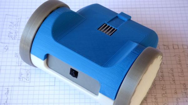
Usually at Hackaday we like to post projects that are of interest because of their complexity. That’s especially true for robots — the more motors and sensors the better. But, occasionally we come across a project that’s beautiful because of its simplicity. That’s the case with [Max Kern]’s ZeroBot, recently posted over on Hackaday.io.

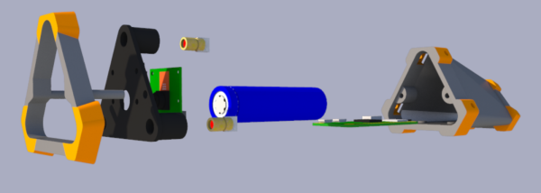
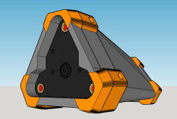
The ZeroBot breaks the essence of a robot down to just the essentials: a Raspberry Pi Zero W for the brains, a driver and two motors for movement, a battery for power, and a camera to see. The chassis is made completely of parts that are easily 3D-printable. The Zero W creates a WiFi access point that users can connect to on a computer or smart phone, and subsequently provides FPV control.

This project is reminiscent of the starter robot kits many of us began our hacking lives with, and it’s a great teaching tool for kids. Print the parts and you can have the robot built-in an afternoon, while still being fun enough to actually play with when you’re done. After the physical robot is built, the possibilities for programming and controlling it are endless.

Continue reading “ZeroBot Is As Simple As It Gets”

Hackaday Prize Entry: Rangefinder + Camera = SmartZoom

The interesting thing about submissions for The Hackaday Prize is seeing unusual projects and concepts that might not otherwise pop up. [ken conrad] has a curious but thoughtfully designed idea for Raspberry Pi-based SmartZoom Imaging that uses a Pi Zero and camera plus some laser emitters to create a device with a very specific capability: a camera that constantly and dynamically resizes the image make the subject appear consistently framed and sized, regardless of its distance from the lens. The idea brings together two separate functions: rangefinding and automated zooming and re-sampling of the camera image.

The Raspberry Pi uses the camera board plus some forward-pointing laser dots as a rangefinder; as long as at least two laser dots are visible on the subject, the distance between the device and the subject can be calculated. The Pi then uses the knowledge of how near or far the subject is to present a final image whose zoom level has been adjusted to match (and offset) the range of the subject from the camera, in effect canceling out the way an object appears larger or smaller based on distance.

We’ve seen visible laser dots as the basis of rangefinding before, but never tied into a zoom function. Doubtlessly, [ken conrad] will update his project with some example applications, but in the meantime we’re left wondering: is there a concrete, practical use case for this unusual device? We have no idea, but we’d certainly have fun trying to find one.

The Raspberry Pi As An IR To WiFi Bridge

[Jason] has a Sonos home sound system, with a bunch of speakers connected via WiFi. [Jason] also has a universal remote designed and manufactured in a universe where WiFi doesn’t exist. The Sonos can not be controlled via infrared. There’s an obvious problem here, but luckily tiny Linux computers with WiFi cost $10, and IR receivers cost $2. The result is an IR to WiFi bridge to control all those ‘smart’ home audio solutions.

The only thing [Jason] needed to control his Sonos from a universal remote is an IR receiver and a Raspberry Pi Zero W. The circuit is simple – just connect the power and ground of the IR receiver to the Pi, and plug the third pin of the receiver into a GPIO pin. The new, fancy official Raspberry Pi Zero enclosure is perfect for this build, allowing a little IR-transparent piece of epoxy poking out of a hole designed for the Pi camera.

For the software, [Jason] turned to Node JS, and LIRC, a piece of software that decodes IR signals. With the GPIO pin defined, [Jason] set up the driver and used the Sonos HTTP API to send commands to his audio unit. There’s a lot of futzing about with text files for this build, but the results speak for themselves: [Jason] can now use a universal remote with everything in his home stereo now.

Pi Zero W Impersonates IPhone, Becomes Terminal

There’s something to be said for economies of scale and few things sell more than cell phones. Maybe that’s why [NODE] took inspiration from an iPhone slide out keyboard case to create this Pi Zero W-based portable terminal. This is actually his third iteration, and in the video below he explains why he has built the new version.

By housing the custom bits in a 3D-printed frame that is size compatible with the iPhone, [NODE] manages to leverage the slick slide out keyboard cases available for the phone. The iPhone in question is an older iPhone 5, so the cases are inexpensive, compared to the latest generation. On the other hand, the iPhone 5 is recent enough that it shouldn’t be hard to find a compatible case.

The circuitry itself is pretty straightforward: a battery, a charge controller, and an LCD display. The only complaint we could see was the lack of a control key on the keyboard.

Continue reading “Pi Zero W Impersonates IPhone, Becomes Terminal”

Raspberry Pi-Based Game Boy Emulator

The most popular use for a Raspberry Pi, by far, is video game emulation. We see this in many, many forms from 3D printed Raspberry Pi cases resembling the original Nintendo Entertainment System to 3D printed Raspberry Pi cases resembling Super Nintendos. There’s a lot of variety out there for Raspberry Pi emulation, but [moosepr] is taking it to the next level. He’s building the smallest Pi emulation build we’ve ever seen.

This build is based on the Pi Zero and a 2.2″ (0.56 dm) ili9341 TFT display. This display has a resolution of 240×320 pixels, which is close enough to the resolution of the systems the Pi Zero can emulate. The Pi Zero and display are attached to a beautiful purple breakout board (shared on OSH Park) along with a few 5-way nav switches, a charger for a Lipo battery, and a few other bits and bobs.

Right now, [moosepr] is experimenting with adding sound to his board. It’s easy enough to get sound out of a Pi Zero — it’s just PWM coming from a few pins — but audio also needs an amp, a speaker, and more space on the board. To solve this problem, [moose] found a few piezo transducers from musical greeting cards. These are designed to be thin and as loud as possible, and attaching these directly to the PWM pins providing audio might just work. This is a project to keep an eye on, if only to see if cheap piezos work for low-fi audio in retro emulators.