[Camus] had it all wrong. After a few hundred years of rolling a stone up a mountain, Sisyphus would do what all humans would do: become engrossed in novelty. The stone would never reach the summit, but it could roll off some pretty sweet ramps. That mountain goat that ticked him off a few decades ago? If Sisyphus let go right now, the stone would probably take that goat out. Sisyphus, like all of us, would be consumed in meaningless novelty. One must imagine Sisyphus happy.
The pumpkin spice must flow. It’s the holidays and for a lot of us that means copious amounts of baked goods. How about an edible sandworm? It looks like something close to a cinnamon roll.
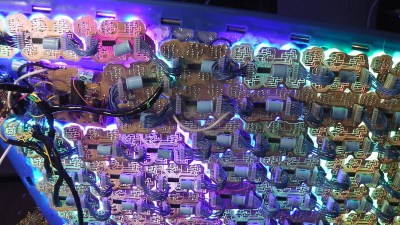
This December’s Marie Claire – whatever that is, I have no idea – features haute circuits. These circuit boards are the work of [Saar Drimer] and Boldport, makers of fine circuit board art. We’ve seen his work a number of times featuring squiggly traces and backlit panels. This seems to be the first time Boldport and the entire idea of PCB art has infiltrated the design world. He also does puzzles.
Raspberry Pi cases simply do not look cool. There’s ports coming out everywhere, and plastic really doesn’t look that great. You know what does look great? Walnut. [Karl] made a few of these out of walnut, MDF and solid aluminum. He’s thinking he might bring this to market, you can check out his webzone here.
Self-driving cars being sold right now! That’s an eBay link for a DARPA Grand Challenge vehicle, a heavily modified Isuzu VehiCross loaded up with computers, a laser scanner, camera, and connected to actuators for steering, brake, pedals, and shifter.
A few years ago, a snowboarding company realized they could use YouTube as a marketing device. They made some really cool projects, like a snowboard with battery-powered heaters embedded in the core of the board (yes, it works). There’s only so many different snowboards you can build, so they turned to surfboards. In fact, they turned to cardboard surfboards, and last week they made a cardboard electric guitar in the Fender custom shop. It’s a completely understandable linear progression from A to B to I don’t know what kind of glue they’re using.