Programmable Resistance Box

For prototype electronics projects, most of us have a pile of resistors of various values stored somewhere on our tool bench. There are different methods of organizing them for easy access and identification, but for true efficiency a resistance substitution box can be used on the breadboard to quickly change resistance values at a single point in a circuit. Until now it seemed this would be the pinnacle of quickly selecting differently-sized resistors, but thanks to this programmable resistor bank there’s an even better option available now.

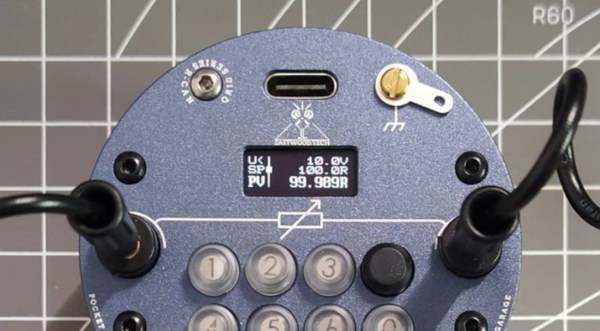
Unlike a traditional substitution box or decade box, which uses switches or dials to select different valued resistors across a set of terminals, this one is programmable and uses a series of sealed relays instead. That’s not where the features stop, though. It also comes equipped with internal calibration circuitry which take into account the resistance of the relay contacts and internal wiring to provide a very precise resistance value across its terminals. It’s also able to be calibrated manually to account for temperature or other factors.

For an often-overlooked piece of test equipment, this one surely fits the bill of something we didn’t know we needed until now. Even though digital resistor substitution boxes are things we have featured in the past, the connectivity and calibration capabilities of this one make it intriguing.

Re-imagining The Resistor Color Code Cheat Sheet

Some people look at a venerable resource like resistor color code charts and see something tried and true, but to [Andrew Jeddeloh], there’s room for improvement. A search for a more intuitive way is what led to his alternate cheat sheet for resistor color codes.

Color code references typically have a reader think of a 560 kΩ resistor as 56 * 10 kΩ, but to [Andrew], that’s not as simple as it could be. He suggests that it makes more sense for a user to start with looking up the colors to make 5.6 (green-blue), then simply look up that a following yellow band means resistance in the 100 kΩ range (assuming a four-band resistor); therefore 560 kΩ is green-blue-yellow.

The big difference is that the user is asked to approach 560 kΩ not as 56 * 10 kΩ, but as 5.6 * 100 kΩ. [Andrew] shares a prototype of a new kind of chart in his post, so if you have a few minutes, take it for a spin and see what you think.

Is his proposed method more intuitive, or less? We think [Andrew] makes a pretty good case, but you be the judge. After all, just because something has always been so doesn’t mean there isn’t room for improvement. This happens to apply nicely to resistors themselves, in fact. It may seem like through-hole resistors have always had color bands, but that is not the case.

A Perfect Clock For Any Hacker’s Ohm

The vast majority of us are satisfied with a standard, base ten display for representing time. Fewer of us like to be a bit old-fashioned and use a dial with a couple of hands that indicate the time, modulo twelve. And an even smaller minority, with a true love for the esoteric, are a fan of binary readouts. Well, there’s a new time-telling game in town, and as far as we’re concerned it’s one of the best ones yet: resistor color codes.

The Ohm Clock is, as you may have guessed, a giant model of a resistor that uses its color bands to represent time.  
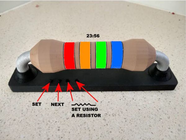
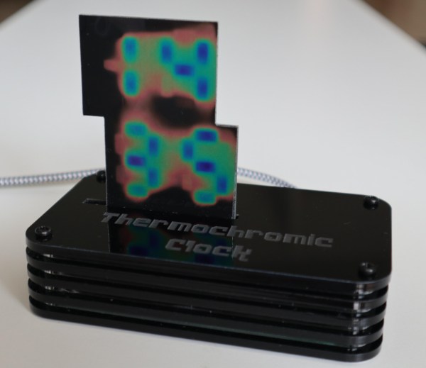
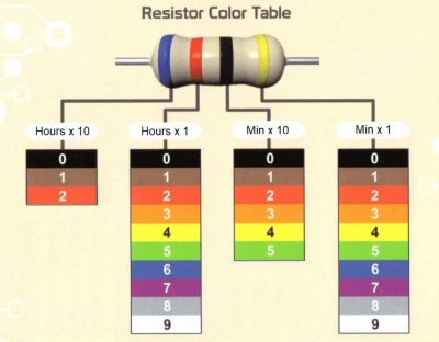
Each of the four bands represents a digit in the standard HH:MM representation of time, and for anybody well-versed in resistor codes this is sure to be a breeze to read. The clock itself was designed by [John Bradnam]. It’s body is 3D printed, with RGB LEDs to brightly illuminate each segment. The whole thing is controlled by an old favorite – an ATtiny, supported by a Real Time Clock (RTC) chip for accurate timekeeping.

You can set the time in the traditional fashion using buttons, or — and here’s the brilliant part — you can use a resistor. Yup, that’s right. Connecting a 220 Ohm resistor across two terminals on the clock will set the time to 2:20. Genius.

When you come across an art as old as timekeeping, it’s easy to assume that everything’s already been done. We have sundials, hourglasses, analog clocks, digital watches, those cool clocks that use words instead of numbers, the list goes on. That’s why it’s so exciting to see a new (and fun!) idea like this one emerge.

Using Heaters To Display Time

We’re always fans of interesting clock builds around here, whether it’s a word clock, marble clock, or in this case a clock using a unique display method. Of course, since this is a build by Hackaday’s own [Moritz v. Sivers] the display that was chosen for this build was a custom thermochromic display. These displays use heat-sensitive material to change color, and his latest build leverages that into one of the more colorful clock builds we’ve seen.

The clock’s display is built around a piece of thermochromic film encased in clear acrylic. The way the film operates is based on an LCD display, but using heat to display the segments. For this build, as opposed to his previous builds using larger displays, he needed to refine the method he used for generating the heat required for the color change. For that he swapped out the Peltier devices for surface mount resistors and completely redesigned the drivers and the PCBs around this new method.

Of course, the actual clock mechanism is worth a mention as well. The device uses an ESP8266 board to handle the operation of the clock, and it is able to use its wireless capabilities to get the current time via NTP. All of the files needed to recreate this are available on the project page as well, including code, CAD files, and PCB layouts. It’s always good to have an interesting clock around your home, but if you’re not a fan of electronic clocks like this we can recommend any number of mechanical clocks as well.

Continue reading “Using Heaters To Display Time”

Status Display Lets Them Know You Can’t Play

All this ongoing forced togetherness is great, but sometimes you just need to be able to pretend you’re alone so you can get some work done. So, how do you keep family members out of your home office? Our own [Bob Baddeley]’s free/busy indicator is about as simple as it gets.

The best part is that the status can been seen on both sides of the door so you don’t forget to keep it updated. Or maybe it’s the super-low part count. There’s no BLE, LoRa, or Wi-Fi, just two sets of red and green LEDs, a three-way switch, and a power source. Well, and current-limiting resistors of course.

[Bob] already had all the components on hand, including the nifty enclosure, which is another great thing about this build. Like [Bob] says, you could house the control side of this circuit in just about anything you’ve got lying around.

Young children might abuse this one, but this status indicator that lets the family request your presence with the push of a button.

Check Your Pockets For Components

The ideal component tester is like a tricorder for electronics — it can measure whatever it is that you need it to, all the time. Maybe you have a few devices like an ohmmeter and maybe a transistor socket on our multimeter. But what do you do when you need to see if that thyristor is faulty? [Akshay Baweja] wants an everything-tester at the ready, so he’s building a comprehensive device that fits in a pocket. It will identify the type and size of: Continue reading “Check Your Pockets For Components”

Otis Boykin’s Precision Passives Propelled The Pacemaker

The simplest ideas can be the ones that change the world. For Otis Boykin, it was a new way to make wirewound precision resistors. Just like that, he altered the course of electronics with his ideas about what a resistor could be. Now his inventions are in everything from household appliances and electronics to missile guidance computers.

While we like to geek out about developments in resistor tech, Otis’ most widely notable contribution to electronics is the control unit he designed for pacemakers, which regulate a person’s heartbeat. Pacemakers are a real-time clock for humans, and he made them more precise than ever.

Street Smarts and Book Smarts

Otis Frank Boykin was born August 29th, 1920 in Dallas, Texas to Sarah and Walter Boykin. Otis’ father was a carpenter who later became a preacher. His mother Sarah was a maid, and she died of heart failure when Otis was only a year old.

Continue reading “Otis Boykin’s Precision Passives Propelled The Pacemaker”