To say that the process of installing a magnetic resonance imager in a hospital is a complex task is a serious understatement. Once the approval of regulators is obtained, a process that could take years, architects and engineers have to figure out where the massive machine can be installed. An MRI suite requires a sizable electrical service to be installed, reinforced floors to handle the massive weight of the magnet, and special shielding in the walls and ceiling. And once the millions have been spent and the whole thing is up and running, there are ongoing safety concerns when working around a gigantic magnet that can suck ferromagnetic objects into it at any time.
MRI studies can reveal details of diseases and injuries that no other imaging modality can match, which justifies the massive capital investments hospitals make to obtain them. But what if MRI scanners could be miniaturized? Is there something inherent in the technology that makes them so massive and so expensive that many institutions are priced out of the market? Or has technology advanced far enough that a truly portable MRI?
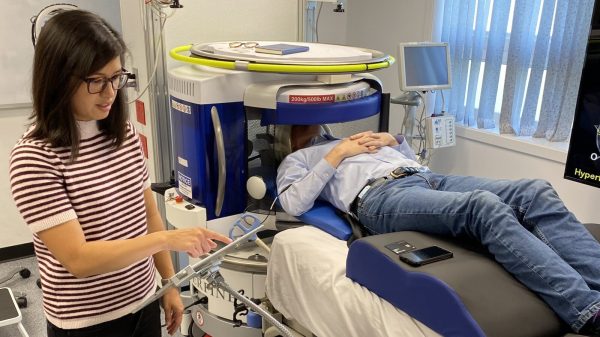
It turns out that yes, an inexpensive MRI scanner is not only possible, but can be made portable enough to wheel into a patient care room. It’s not without compromise, but such a device could make a huge impact on diagnostic medicine and extend MRI technologies into places far beyond the traditional hospital setting.
Continue reading “Portable MRI Machine Comes To The Patient”