While our desktop machines are largely limited to various types of plastic, 3D printing in other materials offers unique benefits. For example, printing with concrete makes it possible to quickly build houses, and we’ve even seen things like sugar laid down layer by layer into edible prints. Metals are often challenging to print with due to its high melting temperatures, though, and while this has often been solved with lasers a new method uses induction heating to deposit the metals instead.
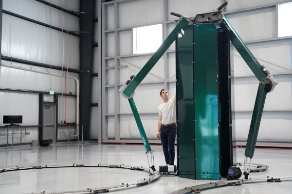
A company in Arizona called Rosotics has developed a large-scale printer based on this this method that they’re calling the Mantis. It uses three robotic arms to lay down metal prints of remarkable size, around eight meters wide and six meters tall. It can churn through about 50 kg of metal per hour, and can be run off of a standard 240 V outlet. The company is focusing on aerospace applications, with rendered rocket components that remind us of what Relativity Space is working on.
The induction heating method for the feedstock not only means they can avoid using power-hungry and complex lasers to sinter powdered metal, a material expensive in its own right, but they can use more common metal wire feedstock instead. In addition to being cheaper and easier to work with, wire is also safer. Rosotics points out that some materials used in traditional laser sintering, such as powdered titanium, are actually explosive.
Of course, the elephant in the room is that Relativity recently launched a 33 meter (110 foot) tall 3D printed rocket over the Kármán line — while Rosotics hasn’t even provided a picture of what a component printed with their technology looks like. Rather than being open about their position in the market, the quotes from CEO Christian LaRosa make it seem like he’s blissfully unaware his fledgling company is already on the back foot.
If you’ve got some rocket propellant tanks you’d like printed, the company says they’ll start taking orders in October. Though you’ll need to come up with a $95,000 deposit before they’ll start the work. If you’re looking for something a little more affordable, it’s possible to convert a MIG welder into a rudimentary metal 3D printer instead.