It probably won’t come as much of a surprise to find that most of the Hackaday staff aren’t exactly what you’d call sports fanatics, so we won’t judge if you didn’t tune in for the Super Bowl last week. But if you did, perhaps you noticed Ring’s Orwellian “Search Party” spot — the company was hoping to get customers excited about a new feature that allows them to upload a picture of their missing pet and have Ring cameras all over the neighborhood search for a visual match. Unfortunately for Ring, the response on social media wasn’t quite what they expected.
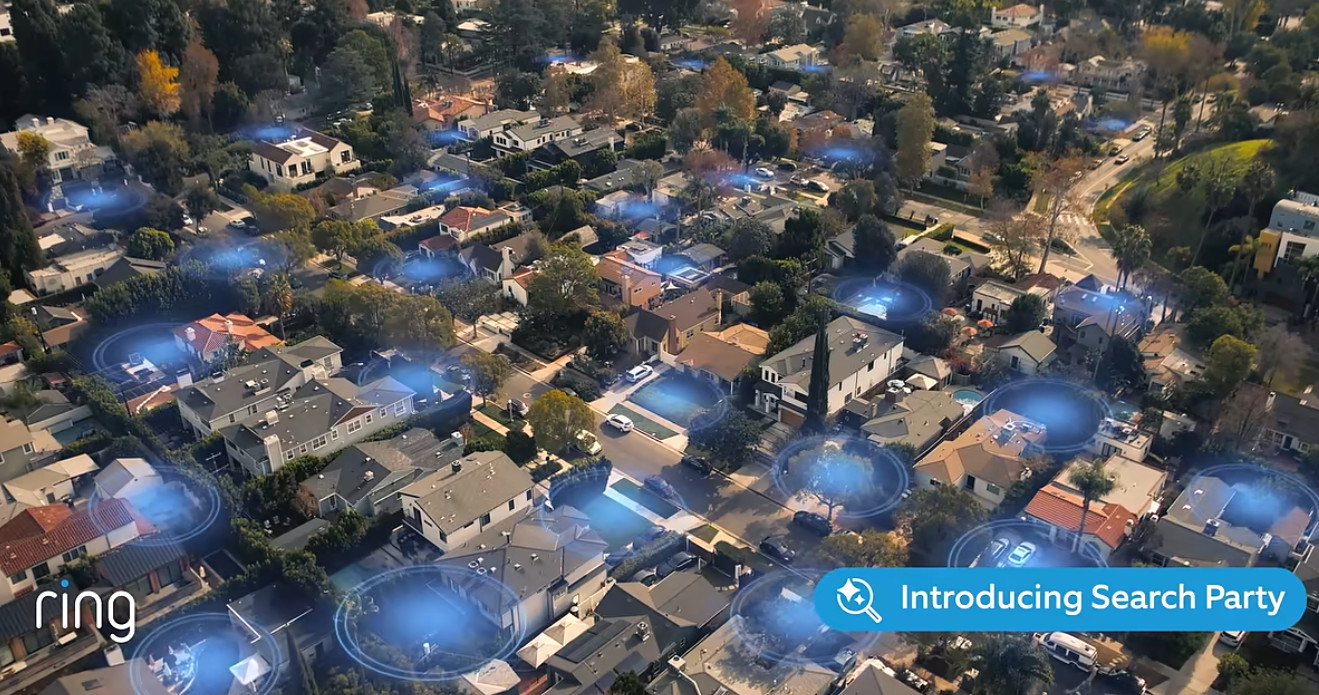
One commenter on YouTube summed it up nicely: “This is like the commercial they show at the beginning of a dystopian sci-fi film to quickly show people how bad things have gotten.” You don’t have to be some privacy expert to see how this sort of mass surveillance is a slippery slope. Many were left wondering just who or what the new system would be searching for when it wasn’t busy sniffing out lost pups.
The folks at Wyze were quick to capitalize on the misstep, releasing their own parody ad a few days later that showed various three-letter agencies leaving rave reviews for the new feature. By Thursday, Ring announced they would be canceling a planned expansion that would have given the divisive Flock Safety access to their network of cameras. We’re sure it was just a coincidence.
Speaking of three-letter agencies, the Environmental Protection Agency has announced this week that they will no longer incentivize the inclusion of stop-start systems on new automobiles. The feature, which shuts off the engine when the vehicle comes to a stop, was never actually required by federal law; rather, the EPA previously awarded credits to automakers that added the feature, which would help them meet overall emission standards. Manufacturers are free to continue offering stop-start systems on their cars if they wish, but without the EPA credits, there’s little benefit in doing so. Especially since, as Car and Driver notes, it seems like most manufacturers are happy to be rid of it. The feature has long been controversial with drivers as well, to the point that we’ve seen DIY methods to shut it off.