Voltage Monitor Relay Is More Than Meets The Eye

Automotive components that have a hidden secondary function are usually limited to cartoons and Michael Bay movies, but this project that [Jesus Echavarria] created for a client is a perhaps as close as we’re likely to get in the near future. The final product certainly looks like a standard automotive relay, but a peek inside the 3D printed case reveals a surprisingly complex little device. It’s still technically a relay, but it uses a PIC microcontroller to decide when it should activate.

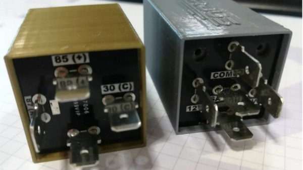
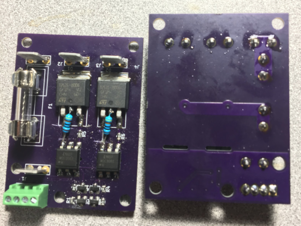
[Jesus] was given the task of creating a device that would fit into the relay box of a vehicle, and serve as a battery monitor to fire off at different voltage set points. The client also wanted the ability to configure such things as how long the device would wait before enabling and disabling the alarms once the voltage threshold has been passed. After showing the client an oversize prototype using a PIC16F88 and switching regulator, he got the OK to move on to a smaller and more cost-effective version.

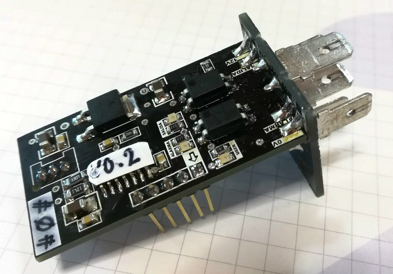
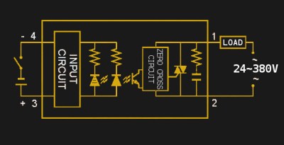
The final hardware makes use of a 78M05 500 mA linear regulator, a PIC16F1824 microcontroller, and a pair of AQY211EH solid state relays. The standard five pin layout used for automotive relays allows the monitor to get power from the vehicle’s battery while providing two output channels that can be switched on and off from the microcontroller. [Jesus] says an agreement with the client prevents him from sharing some elements of the project (like the firmware source code), but he gives enough information that it shouldn’t be too hard to spin up your own version.

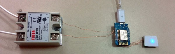
With the addition of something like an ESP8266, this could be an easy way to retrofit an older vehicle with “smart” features. As an example, it could potentially allow for controlling the car’s headlights and horn over Wi-Fi. Or you could hack together a theft deterrent system that refuses to power on the starter or fuel pump unless your smartphone enables the relay first.

DIY SSR For Mains Switching

Typical power strips have their sockets tightly spaced. This makes it cumbersome to connect devices whose wall warts or power bricks are bulky — you end up losing an adjoining socket or two. And if the strip has a single power switch, you cannot turn off individual devices without unplugging them.

Planning to tackle both problems together, [Travis Hein] built himself some custom Dual SSR Controlled Socket Outlets for his workbench. He also decided to add remote switching ability so he could turn off individual sockets via a controller, Raspberry Pi, smartphone app or most ideally, a nice control panel on his desk consisting of a bank of switches.

The easiest solution for his problem would have been to just buy some off-the-shelf SSR or relay modules and wire them up inside his sockets. But he couldn’t find any with the features he wanted, and SSR’s were a little bit on the expensive side. Also, we wouldn’t have a project to write about – sometimes even the simple ones can show us a thing or two.

For starters, he walks us through a quick and simplified primer on figuring out thermal dissipation for the triacs which will be used on his boards. This is tricky since the devices are connected directly to utility voltage so he needs to take care of track clearances, mechanical separation as well as safety. However, for his first board prototypes, he did not add any heat sinking for the triacs, thereby limiting their use to low current loads. Since the SSR also needs to have a wide control voltage range, he describes how the two transistor constant-current input block works to limit opto-triac LED current over a range of 2 V to 30 V.

Before he moves on to his next prototype, [Travis] is looking for feedback to improve his design, make it safer, and figure out if it can pass safety protocols. Let him know via comments below.

Digital Kiln

A kiln or foundry is too often seen as a piece of equipment which is only available if a hackspace is lucky enough to have one or individuals are dedicated enough to drop the cash for one of their own. [The Thought Emporium] thought that way until he sourced materials to make his own kiln which can also be seen after the break. It costs half the price of a commercial model not including a failed—and exploded—paint can version.

As described in the video, these furnaces are tools capable of more than just pottery and soft metal baubles. Sure, a clay chess set would be cool but what about carbon fiber, graphene, aerogel, and glass? Some pretty hot science happens at high temperatures.

We get a nice walk-through of each part of the furnace starting with the container, an eleven-gallon metal tub which should set the bar for the level of kiln being built. Some of the hardware arrangements could be tweaked for safety and we insist that any current-carrying screw is safely mounted inside an enclosure which can’t be opened without tools. There’s good advice about grounding the container if metal is used. The explanation of PID loops can be ignored.

What else can you do with a kiln? How about jewelry, heat treating metal, or recycle your beer cans into an engine.

Continue reading “Digital Kiln”

Repair Job Fixes Compressor, Gets It Online

We’ll never cease to be amazed at the things people try to put on the Internet of Things. Some are no-brainers, like thermostats, security cameras, and garage door openers. Others, like washing machines and refrigerators, are a little on the iffy side, but you can still make a case for them. But an IoT air compressor? What’s the justification for such a thing?

As it turns out, [Boris van Galvin] had a pretty decent reason for his compressor hacks, and it appears that the IoT aspect was one of those “why not?” things. Having suffered the second failure of his compressor’s mechanical pressure switch in a year, and unwilling to throw good money after the $120 that went into replacing the first contactor, [Boris] looked for a cheaper and more interesting way to control the compressor. An ESP8266 dev board made interfacing the analog pressure sensor a snap, and while he was at it, [Boris] added a web interface with a nice graphical air pressure gauge and some on-off controls. Now he can set the pressure using his phone and switch it off in the middle of the night without going outside. That’s an IoT win right there.

No air compressor? No worries — build your own from an old fridge. The non-IoT kind, preferably.

An Introduction To Solid State Relays

When we think of relays, we tend to think of those big mechanical things that make a satisfying ‘click’ when activated. As nice as they are for relay-based computers, there are times when you don’t want to deal with noise or the unreliability of moving parts. This is where solid-state relays (SSRs) are worth considering. They switch faster, silently, without bouncing or arcing, last longer, and don’t contain a big inductor.

Source Fotek SSR Specifications Sheet

An SSR consists of two or three standard components packed into a module (you can even build one yourself). The first component is an optocoupler which isolates your control circuit from the mains power that you are controlling. Second, a triac, silicon controlled rectifier, or MOSFET that switches the mains power using the output from the optocoupler. Finally, there is usually (but not always) a ‘zero-crossing detection circuit’. This causes the relay to wait until the current it is controlling reaches zero before shutting off. Most SSRs will similarly wait until the mains voltage crosses zero volts before switching on.

If a mechanical relay turns on or off near the peak voltage when supplying AC, there is a sudden drop or rise in current. If you have an inductive load such as an electric motor, this can cause a large transient voltage spike when you turn off the relay, as the magnetic field surrounding the inductive load collapses. Switching a relay during a peak in the mains voltage also causes an electric arc between the relay terminals, wearing them down and contributing to the mechanical failure of the relay.

Continue reading “An Introduction To Solid State Relays”

Building An IoT Drill Press For Reasons Unknown

He’s a little cagey about the reasons, but [Ivan Miranda] plans to put a drill press on the internet. What could go wrong with that?

We’ll take [Ivan] at his word that there’s a method to this madness and just take a look at the build itself, in the hopes that it will inspire someone to turn their lowly drill press into a sorta-kinda 2-axis milling machine. [Ivan] makes extensive use of his 3D printer to fabricate the X-axis slide that bolts to the stock drill press table. And before anyone points out the obvious, [Ivan] already acknowledges that the slide is way too flimsy to hold up to much serious drilling, especially considering the huge mechanical advantage of the gearing he used to replace the quill handle for a powered Z-axis. The motor switch was also replaced with a solid state relay. The steppers, relay, and limit switches are all fed into a Teensy that talks to an ESP8266, which will presumably host a web interface to put this thing online.

The connected aspects of the drill press become a little more clear after the break.

Continue reading “Building An IoT Drill Press For Reasons Unknown”

The Internet Of Reflow Ovens

Using a toaster oven to reflow solder isn’t a new idea. But [Sukasa] wanted something that had more features and improved appearace. So he married a Netduino, a toaster oven, and some solid state relays to made a clean-looking reflow oven. His goal was to have nothing look like an overt modification to a casual observer. Inside, however, the oven now has a network connection for system status via a Web browser or JSON.

The new brains of the oven are a Netduino Plus 2 and an I2C port expander that connects to a few extra I/O devices. The challenging I/O, though, is the heaters. When cold, the oven can draw over 16 amps, so a pair of 12A solid state relays in parallel handle that load. There are also two fans: one to keep the electronics cool and another on software control. An IGBT allows the controller to pulse width modulate the fan’s output. A pair of MAX31855s read the thermocouples that report the temperature.

lcd
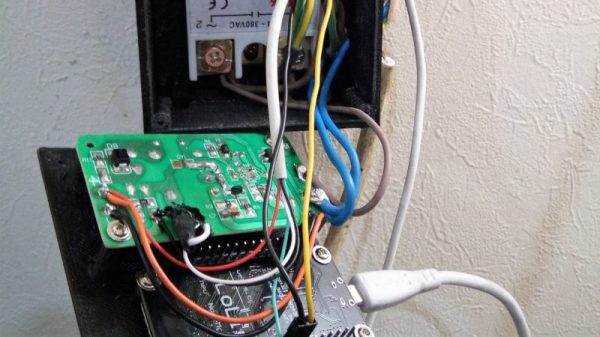
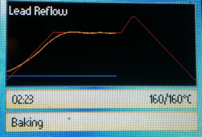
The controller was a mashup of the existing oven’s keypad and an add-on LCD display (see right). One thing we didn’t see was a schematic. Of course, you can read the code and figure out how it is all connected and (unless you use the exact same oven) you are probably going to need to modify things to suit your particular setup, anyway.

We’ve seen other good looking reflow oven and controller builds in the past, including one with a touchscreen. It is also worth noting that you can find reflow ovens at relatively low prices now if you don’t feel like rolling your own.