Hacking Your Way To A Custom TV Boot Screen

More and more companies are offering ways for customers to personalize their products, realizing that the increase in production cost will be more than made up for by the additional sales you’ll net by offering a bespoke product. It’s great for us as consumers, but unfortunately we’ve still got a ways to go before this attitude permeates all corners of the industry.

[Keegan Ryan] recently purchased a TV and wanted to replace its stock boot screen logo with something of his own concoction, but sadly the set offered no official way to make this happen. So naturally he decided to crack the thing open and do it the hard way The resulting write-up is a fascinating step by step account of the trials and tribulations that ultimately got him his coveted custom boot screen, and just might be enough to get you to take a screw driver to your own flat panel at home.

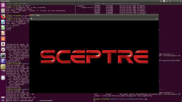
The TV [Keegan] brought was from a brand called SCEPTRE, but as a security researcher for NCC Group he thought it would be a fun spin to change the boot splash to say SPECTRE in honor of the infamous x86 microarchitecture attack. Practically speaking it meant just changing around two letters, but [Keegan] would still need to figure out where the image is stored, how it’s stored, and write a modified version to the TV without letting the magic smoke escape. Luckily the TV wasn’t a “smart” model, so he figured there wouldn’t be much in the way of security to keep him from poking around.

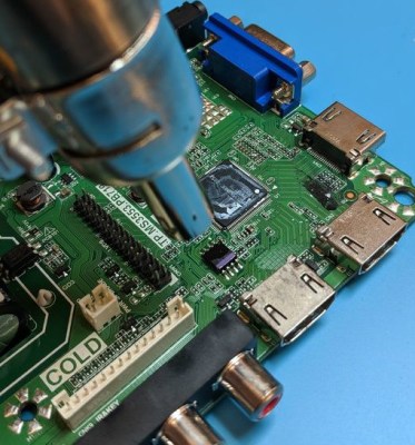
He starts by taking the TV apart and studying the main PCB. After identifying the principle components, he deduces where the device’s firmware must be stored: an 8 MB SPI flash chip from Macronix. He connects a logic analyzer up to the chip, and sure enough sees that the first few kilobytes are being read on startup. Confident in his assessment, he uses his hot air rework station to lift the chip off the board so that he can dive into its contents.

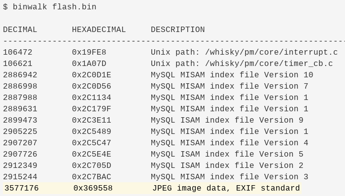
With the help of the trusty Bus Pirate, [Keegan] is able to pull the chip’s contents and verify its integrity by reading a few human-readable strings from it. Using the binwalk tool he’s able to identify a JPEG image within the firmware file, and by feeding its offset to dd, pull it out so he can view it. As hoped, it’s the full screen SCEPTRE logo. A few minutes in GIMP, and he’s ready to merge the modified image with the firmware and write it back to the chip.

He boots the TV back up and finds…nothing changed. A check of the datasheet for the SPI flash chip shows there are some protection bits used to prevent modifying particular regions of the chip. So after some modifications to the Bus Pirate script and another write, he boots the TV and hopes for the best. Finally he sees the object of his affection pop up on the big screen, a subtle change that reminds him every time the TV starts about the power of reverse engineering.

Blazing Fast Raspberry Pi Display Driver Will Melt Your Face Then Teach You How

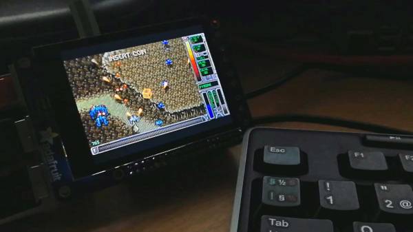
Reader [poipoi] recently wrote into our tip line to tell us about an “amazingly fast” Raspberry Pi display driver with a README file that “is an actual joy to read”. Of course, we had to see for ourselves. The fbcp-ili9341 repo, by [juj], seems to live up to the hype! The software itself appears impressive, and the README is detailed, well-structured, educational, and dare we say entertaining?

The driver’s main goal is to produce high frame rates — up to around 60 frames per second — over an SPI bus, and it runs on various Raspberry Pi devices including the 2, 3 and Zero W. Any video output that goes to the Pi’s HDMI port will be mirrored to a TFT display over the SPI bus. It works with many of the popular displays currently out there, including those that use the ILI9341, ILI9340, and HX8357D chipsets.

The techniques that let [juj] coax such frame rates out of a not-terribly-fast serial bus are explained in detail in the README’s How it Works section, but much of it boils down to the fact that it’s only sending changed pixels for each frame, instead of the full screen. This cuts out the transmission of about 50% of the pixels in each update when you’re playing a game like Quake, claims the author. There are other interesting performance tweaks as well, so be sure to check out the repo for all the details.

There’s a video comparing the performance of fbcp-ili9341 to mainline SPI drivers after the break.

Continue reading “Blazing Fast Raspberry Pi Display Driver Will Melt Your Face Then Teach You How”

E-ink Typewriter Is Refreshingly Slow

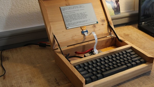
It’s pretty hard to use the internet to complete a task without being frequently distracted. For better or worse, there are rabbit holes at every turn and whilst exploring them can be a delight, sometimes you just need to focus on a task at hand. The solution could be in the form of distraction-blocking software, razor-sharp willpower, or a beautifully crafted modern “typewriter”. The constraint and restriction of a traditional typewriter appealed to [NinjaTrappeur], but the inability to correct typos and share content online was a dealbreaker. A hybrid was the answer, with a mechanical keyboard commanding an E-ink display driven by a Raspberry Pi.

The main point of interest in this build is the E-ink screen. Though it’s easy to acquire theses displays in small sizes, obtaining a screen greater than four inches proved to be a challenge. Once acquired, driving the screen over SPI was easy, but the refresh rate was horrific. The display takes three seconds to redraw, and whilst [NinjaTrappeur] was hoping to implement a faster “partial refresh”, he was unable to read the appropriate values from the onboard flash to enable manual control of the drawing stages. Needless to say, [NinjaTrappeur] asks if people have had success driving these displays at a more usable rate, and would love to hear from you if so.

Some auxiliary hacks come in the form of terminal emulator adaptation, porting the E-ink screen library from C++ to C, and capturing the keyboard input. A handmade wooden case finishes it off.

If it’s old-school typewriters that float your boat, we’ve got you covered: this solenoid-actuated typewriter printer eventually became a musical instrument, and this daisy wheel machine produces ASCII art from a live camera.

[Via Boing Boing]

Trials And Tribulations In Sending Data With Wires

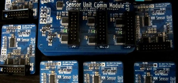
When working on a project that needs to send data from place to place the distances involved often dictate the method of sending. Are the two chunks of the system on one PCB? A “vanilla” communication protocol like i2c or SPI is probably fine unless there are more exotic requirements. Are the two components mechanically separated? Do they move around? Do they need to be far apart? Reconfigurable? A trendy answer might be to add Bluetooth Low Energy or WiFi to everything but that obviously comes with a set of costs and drawbacks. What about just using really long wires? [Pat] needed to connect six boards to a central node over distances of several feet and learned a few tricks in the process.

When connecting two nodes together via wires it seems like choosing a protocol and plugging everything in is all that’s required, right? [Pat]’s first set of learnings is about the problems that happen when you try that. It turns out that “long wire” is another way to spell “antenna”, and if you happen to be unlucky enough to catch a passing wave that particular property can fry pins on your micro.

Plus it turns out wires have resistance proportional to their length (who would have though!) so those sharp square clock signals turn into gently rolling hills. Even getting to the point where those rolling hills travel between the two devices requires driving drive the lines harder than the average micro can manage. The solution? A differential pair. Check out the post to learn about one way to do that.

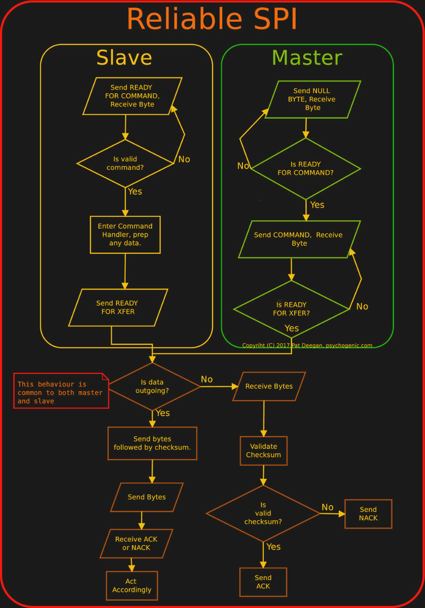
It looks like [Pat] needed to add USB to this witches brew and ended up choosing a pretty strange part from FTDI, the Vinculum II. The VNC2 seemed like a great choice with a rich set of peripherals and two configurable USB Host/Peripheral controllers but it turned out to be a nightmare for development. [Pat]’s writeup of the related troubles is a fun and familiar read. The workaround for an incredible set of undocumented bad behaviors in the SPI peripheral was to add a thick layer of reliability related messaging on top of the physical communication layer. Check out the state machine for a taste, and the original post for a detailed description.

Faded Beauty DMM Gets An OLED Makeover

When a fine piece of lab instrumentation crosses your bench, you’ve got to do your best to put it to work. But even in the highest quality devices no component lasts forever, especially vacuum tubes. For some vintage instruments with vacuum fluorescent displays, that means putting up with less-than-perfect digits in order to get that sweet, sweet precision. Or not – you can always reverse engineer the thing and add a spanking new OLED display.

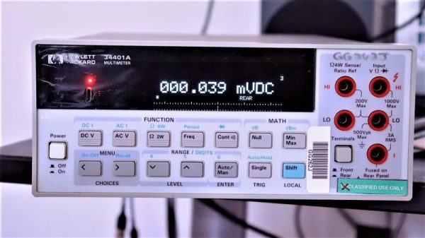
The Hewlett-Packard 34401A digital multimeter that fell into [qu1ck]’s lap was a beauty, but it had clearly seen better days. The display was full of spuriously illuminated dots and segments, making it hard to use the 6.5 digit DMM. After a futile bit of probing to see if a relatively easy driver fix would help, and with a replacement display being made of solid unobtanium, [qu1ck] settled in for the long process of reverse engineering the front panel protocol. As luck would have it, H-P used the SPI protocol to talk to the display, and it wasn’t long before [qu1ck] had a decent prototype working. The final version is much more polished, with a display sized to fit inside the original space occupied by the VFD. The original digits and annunciator icons are recreated, and he added a USB port and the bargraph display show in the clip below.

We think it looks fabulous, and both the firmware and hardware are on Github if you’d like to rescue a similar meter. You may want to check our guide to buying old test gear first, though, to get the most bang for your buck.

Continue reading “Faded Beauty DMM Gets An OLED Makeover”

Digital Attenuator Goes From Manual To Arduino Control

[Kerry Wong] comes across the coolest hardware, and always manages to do something interesting with it. His widget du jour is an old demo board for a digital RF attenuator chip, which can pad a signal in discrete steps according to the settings of some DIP switches. [Kerry]’s goal: forget the finger switch-flipping and bring the attenuator under Arduino control.

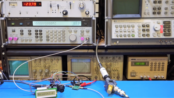
As usual with his videos, [Kerry] gives us a great rundown on the theory behind the hardware he’s working with. The chip in question is an interesting beast, an HMC624LP4E from Hittite, a company that was rolled into Analog Devices in 2014. The now-obsolete device is a monolithic microwave integrated circuit (MMIC) built on a gallium arsenide substrate rather than silicon, and attenuates DC to 6-GHz signals in 64 steps down to -31.5 dBm. After a functional check of the board using the DIP switches, he whipped up a quick Arduino project to control the chip with its built-in serial interface. It’s just a prototype for now, but spinning the encoder is a lot handier than flipping switches, and once this is boxed up it’ll make a great addition to [Kerry]’s RF bench.

If this video puts you in an RF state of mind, check out some of [Kerry]’s other videos, like this one about temperature-compensated crystal oscillators, or the mysteries of microwave electronics.

Continue reading “Digital Attenuator Goes From Manual To Arduino Control”

SPIDriver Shows You What’s Going On

When you’re debugging two bits of electronics talking SPI to each other, there’s a lot that can go sideways. Starting from the ground up, the signals can be wrong: data not synced with clocks right, or phase inverted. On top of that, the actual data sent needs to make sense to the receiving device. Are you sending the right commands?

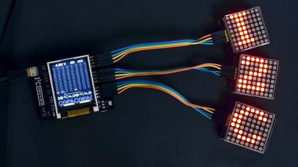
When nothing’s working, you’re fighting simultaneously on these two fronts and you might need different tools to debug each. An oscilloscope works great at the physical layer, while something like a Bus Pirate or fancier logic analyzer works better at the data layer because it can do parsing for you. [James Bowman]’s SPIDriver looks to us like a Bus Pirate with a screen — giving you a fighting chance on both fronts.

SPIDriver also has a couple more tricks up its sleeve: a voltage and current monitor for the device under test, so you don’t even have to break out your multimeter when you’re experiencing random resets. We asked [James] if these additions had a sad history behind them. He included this XKCD.

Everything about SPIDriver is open, so you can check out the hardware design, browse the code, and modify any and all of it to your taste. And speaking of open, [James] is also the man behind the Gameduino and an amazing FPGA Forth soft-CPU.

It’s fully crowd-funded, but it closes in a couple of days so if you want one, get on it soon.

And if you want to learn more about SPI debugging, we’ve written up a crash-course. With the gear and the know-how, you at least stand a fighting chance.