JWST mirror actuator model

Working Model Reveals Amazing Engineering Of Webb’s Mirror Actuators

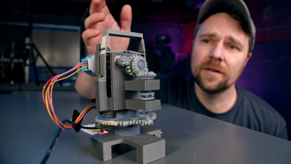
We end up covering a lot of space topics here on Hackaday, not because we’re huge space nerds — spoiler alert: we are — but because when you’ve got an effectively unlimited budget and a remit to make something that cannot fail, awe-inspiring engineering is often the result. The mirror actuators on the James Webb Space Telescope are a perfect example of this extreme engineering, and to understand how they work a little better, [Zachary Tong] built a working model of these amazing machines.

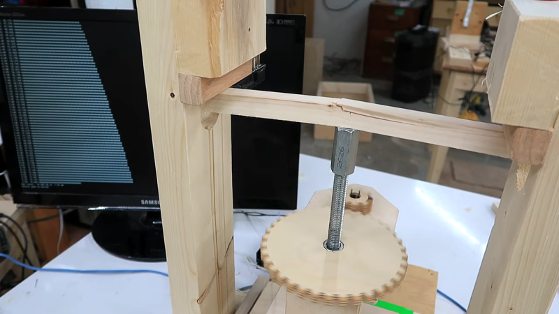
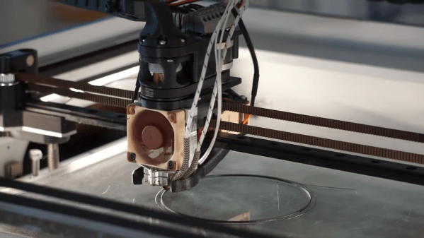
The main mirror of the JWST is made of 18 separate hexagonal sections, the position of each which must be finely tuned to make a perfect reflector. Each mirror has seven actuators that move it through seven degrees of freedom — the usual six that a Stewart platform mechanism provides, plus the ability to deform the mirror’s curvature slightly. [Zach]’s model actuator is reverse-engineered from public information (PDF) made available by the mirror contractor, Ball Aerospace. While the OEM part is made from the usual space-rated alloys and materials, the model is 3D printed and powered by a cheap stepper motor.

That simplicity belies the ingenious mechanism revealed by the model. The actuators allow for both coarse and fine adjustments over a wide range of travel. A clever tumbler mechanism means that only one motor is needed for both fine and coarse adjustments, and a flexure mechanism is used to make the fine adjustments even finer — a step size of only 8 nanometers!

Hats off to [Zach] for digging into this for us, and for making all his files available in case you want to print your own. You may not be building a space observatory anytime soon, but there’s plenty about these mechanisms that can inform your designs.

Continue reading “Working Model Reveals Amazing Engineering Of Webb’s Mirror Actuators”

Wire EDM

Bringing The Power Of EDM To The Home Shop

When you see something made from metal that seems like it would be impossible to manufacture, chances are good it was made with some variety of electrical discharge machining. EDM is the method of choice for hard-to-machine metals, high aspect ratio hole drilling, and precise surface finishes that let mating parts slip together with almost zero clearance. The trouble is, EDM is a bit fussy, and as a result hasn’t made many inroads to the home shop.

[Action BOX] aims to change that with a DIY wire EDM machine. In wire EDM, a fine brass wire is used as an electrode to slowly erode metal in a dielectric bath. The wire is consumable, and has to constantly move from a supply spool through the workpiece and onto a takeup spool. Most of the build shown in the video below is concerned with the wire-handling mechanism, which is prototyped from 3D-printed parts and a heck of a lot of rollers and bearings. Maintaining the proper tension on the wire is critical, so a servo-controlled brake is fitted to the drivetrain, which itself is powered by a closed-loop stepper. Tension is measured by a pair of strain gauges and Arduinos, which control the position of the shaft brake servo and the speed of the motor on the takeup spool.

Unfortunately, in testing this setup proved to live up to EDM’s fussy reputation. The brass wire kept breaking as soon as cutting started, and [Action BOX] never made any actual cuts. There’s certainly promise, though, and we’re looking forward to developments. For more on EDM theory, check out [Ben Krasnow]’s look at EDM hole-drilling.

Continue reading “Bringing The Power Of EDM To The Home Shop”

Electronic leadscrew

Electronic Lead Screws – Not Just For Threading Anymore

An electronic leadscrew is an increasingly popular project for small and mid-sized lathes. They do away with the need to swap gears in and out to achieve the proper ratio between spindle speed and tool carriage translation, and that makes threading a snap. But well-designed electronic leadscrews, like this one from [Hobby Machinist], offer so much more than just easy threading.

The first thing that struck us about this build was the polished, professional look of it. The enclosure for the Nucleo-64 dev board sports a nice TFT display and an IP65-rated keyboard, as well as a beefy-looking jog wheel. The spindle speed is monitored by a 600 pulses-per-revolution optical encoder, and the lathe’s leadscrew is powered by a closed-loop NEMA 24 stepper. This combination allows for the basic threading operations, but the addition of a powered cross slide opens up a ton more functionality. Internal and external tapers are a few keypresses away, as are boring and turning and radius operations, both on the right and on the left. The video below shows radius-cutting operations combined to turn a sphere.

From [Hobby Machinist]’s to-do list, it looks like filleting and grooving will be added someday, as will a G-code parser and controller to make this into a bolt-on CNC controller. Inspiration for the build is said to have come in part from [Clough42]’s electronic leadscrew project from a few years back. Continue reading “Electronic Lead Screws – Not Just For Threading Anymore”

Belt-drive 3D-printer extruder

Back-to-Back Belts Drive Filament In This Unique Extruder Design

It’s hard to say when inspiration will strike, or what form it’ll take. But we do know that when you get that itch, it’s a good idea to scratch it, because you might just end up with something like this cool new design for a 3D printer extruder as a result.

Clearly, the world is not screaming out for new extruder designs. In fact, the traditional spring-loaded, toothed drive wheel on a stepper really does the job of feeding filament into a printer’s hot end just fine, all things considered. But [Jón Schone], aka Proper Printing on YouTube, got the idea for his belt-drive extruder from seeing how filament manufacturers handle their products. His design is a scaled-down version of that, and uses a pair of very small timing belts that run on closely spaced gears. The gears synchronize the movement of the two belts, with the filament riding in the very narrow space between the belts. It’s a simple design, with the elasticity of the belt material eliminating the need for spring pre-loading of the drive gears.

Simple in design, but not the easiest execution. The video below tells [Jón]’s tale of printing woe, from using a viscous specialty SLA resin that was really intended for a temperature-controlled printer, to build tank damage. The completed extruder was also a bit too big to mount directly on the test printer, so that took some finagling too. But at the end of the day, the idea works, and it looks pretty cool doing it.

As for potential advantages of the new design, we suppose that remains to be seen. It does seem like it would eliminate drive gear eccentricity, which we’ve seen cause print quality issues before.

Continue reading “Back-to-Back Belts Drive Filament In This Unique Extruder Design”

Flip-up clock

A Flip Clock That Flips Up, Not Down

The venerable flip clock has become an outsized part of timekeeping culture that belies the simplicity of its mechanism. People collect and restore the electromechanical timepieces with devotion, and even seek to build new kinds of clocks based on split-flap displays. Designs differ, but they all have something in common in their use of gravity to open the leaves and display their numbers.

But what if you turned the flip clock on its head? That’s pretty much what [Shinsaku Hiura] accomplished with a flip clock that stands up the digits rather than flipping them down. The clock consists of three 3D-printed drums that are mounted on a common axle and linked together with gears and a Geneva drive. Each numeral is attached to a drum through a clever cam that makes sure it stands upright when it rotates to the top of the drum, and flops down cleanly as the drum advances. The video below makes the mechanism’s operation clear.

The build instructions helpfully note that “This clock is relatively difficult to make,” and given the extensive troubleshooting instructions offered, we can see how that would be so. It’s not the first time we’ve seen a mechanically challenging design from [Shinsaku Hiura]; this recent one-servo seven-segment display comes to mind.

Continue reading “A Flip Clock That Flips Up, Not Down”

wood strength tester

Shop-Built Rig Measures Strength Of Wood Accurately

Wood is an incredibly versatile material, but like everything else, it has its limits. Build a chair from weak wood and the worst that can happen is probably not that bad. But if you build machine tools from wood, the stakes for using the wrong wood can be a bit higher.

That’s the thinking behind the wood strength testing setup [Matthias Wandel] came up with. Previously, he had a somewhat jury-rigged test setup with a hydraulic bottle jack to apply force to the test piece and a bathroom scale to make measurements. That setup was suboptimal, so version two used a jackscrew to apply the force, but the bathroom scale still left the measurements open to interpretation. Version three, the topic of the video below, went with strain gauges and an A/D converter connected to a Raspberry Pi to automate data collection. The jackscrew was also integrated into the test setup with a stepper motor and, of course, [Matthias]’ famous wooden gears.

While the test rig is pretty simple in design, there’s a lot of subtlety to the calibration to make sure that it’s measuring the test material itself and not just compliance within the mechanism. It’s just another in a long line of data-gathering exercises that [Matthias] seems to groove on, like his recent woodshop electrical explorations.

Continue reading “Shop-Built Rig Measures Strength Of Wood Accurately”

spinning thread extruder

Spinning Threads Put The Bite On Filament In This Novel Extruder Design

When it comes to innovation in FDM 3D printing, there doesn’t seem to be much room left to move the needle. Pretty much everything about filament printing has been reduced to practice, with more or less every assembly available off the shelf. Even the business end — the extruder — is so optimized that there’s not much room left for innovation.

Or is there? The way [David Leitner] sees it, there is, which is why he built this rolling-screw extruder (if you can get to the Thingiverse link, [David] cross-posted on reddit, too). Standard extruders work on the pinch-roller principle, where the relatively soft filament is fed past a spring-loaded gear attached to a stepper motor. The stepper rotates the gear, which either advances the filament into or retracts it from the hot end. [David]’s design instead uses a trio of threaded rods mounted between two rings. The rods are at an angle relative to the central axis of the rings, forming a passage that’s just the right size for the filament to fit in. When the rings spin, the threads on the rods engage with the filament, gripping it around its whole circumference and advancing or retracting it depending on which way it’s spinning. The video below shows it working; we have to admit it’s pretty mesmerizing to watch.

[David] himself admits there’s not much advantage to it, perhaps other than a lower tendency to skip since the force is spread over the entire surface of the filament rather than just a small pinch point. Regardless, we like the kind of thinking that leads to something like this, and we’ll bet there are probably unseen benefits to it. And maybe the extruder actually is a place for innovation after all; witness this modular nozzle swapping system.

Continue reading “Spinning Threads Put The Bite On Filament In This Novel Extruder Design”