Clocks are such mundane objects that it’s sometimes hard for them to grab your attention. They’re there when you need them, but they don’t exactly invite you to watch them work. Unless, of course, you build something like this mechanical flip-segment clock with a captivating exposed mechanism
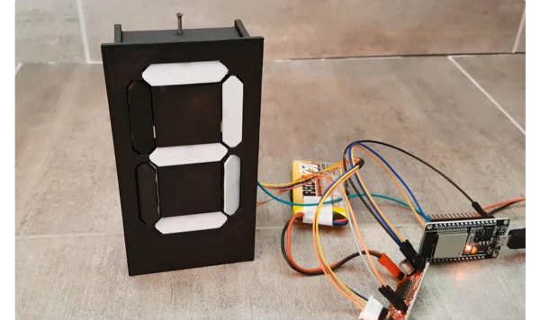
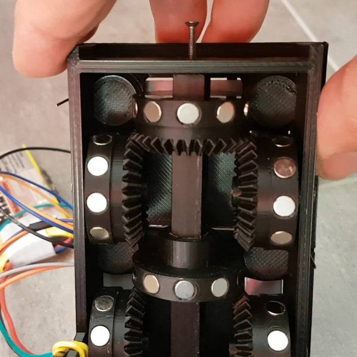
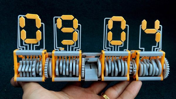
“Eptaora” is the name of this clock, according to its inventor [ekaggrat singh kalsi]. The goal here was to make a mechanical flip-segment display as small as possible, which meant starting with the smallest possible printable screw hole and scaling the design up from there. Each segment is controlled by a multi-lobed cam which bears on a spring-loaded cam follower. When the cam rotates against the follower, a segment is flipped up from the horizontal rest position to the vertical display position. A carryover mechanism connects two adjacent displays so that each pair of digits can be powered by a single stepper, and the finished clock is quite small — a little bit larger than the palm of a hand. The operation seems quite smooth, too, which is always a bonus with clocks such as these. Check out the mesmerizing mechanism in the video below.
We’d have sworn we covered a similar clock before — indeed [ekaggrat] says the inspiration for this clock came from one with a similar mechanism — but we couldn’t find it in the back catalog. Oh sure, there are flip-up digital clocks and all manner of mechanical seven-segment displays, but this one seems to be quite unique, and very pleasing.
Continue reading “Flip-Segment Digital Clock Is A Miniature Mechanical Marvel”