If you thought that Tamagotchis were a late ’90s fad that has faded from most people’s memory by now, you’d be wrong: the franchise is still alive and well today, with new models being released regularly. But even the original model from 1996, known as Tamagotchi P1, is being kept alive by a small group of enthusiasts. When ROM dumps of the original hardware began floating around the internet a couple of years ago, even those without the real thing could run these virtual pets in an emulator.
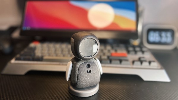
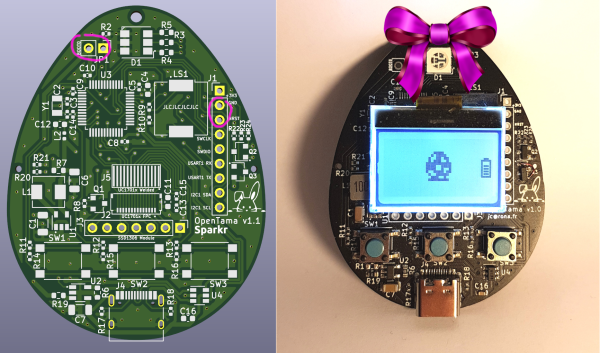
But the whole idea of the Tamagotchi hardware was that it was portable enough to carry around anywhere. If you’re among those who missed that part of the Tamagotchi experience, you’ll be pleased to know that [JC] designed OpenTama: a portable hardware platform that runs an emulated version of the original Tamagotchi P1 software. It’s about as close as it gets to those first-generation virtual pets, but with several additions that make your life easier.
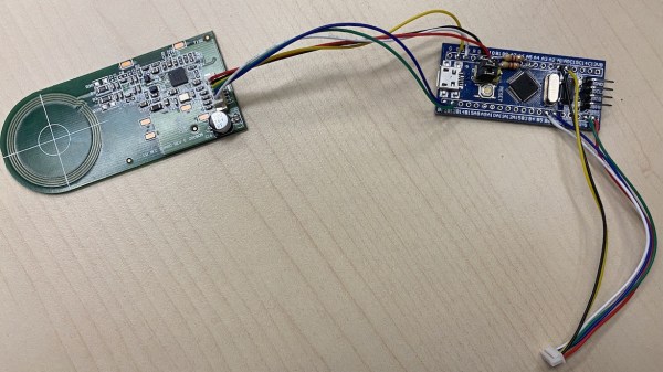
The software platform is [JC]’s TamaLib which we featured last year; in effect it’s an open-source emulator that allows the Tamagotchi ROM to run on a variety of modern hardware platforms. It also contains several additional options like the ability to save and restore your progress or to select customized ROMs. The OpenTama hardware, meanwhile, is a proper 21st-century reimplementation of the original: a small, egg-sized PCB sporting an STM32 microcontroller driving an LCD or OLED display, powered by a 100 mAh battery that can be recharged through a USB-C port.
OpenTama is not limited to the TamaLib software, either: as an open-source general-purpose platform, it can also be used as a learning tool for embedded programming, so if you’ve always wanted to program your own virtual pet, or are simply looking to build a fancy egg timer, OpenTama’s GitHub page is the way to go. We’ve seen quite a few neat Tamagotchi-like projects recently: this 3D-printed one comes with a nice retro LCD screen, while this one’s giant size ensures you don’t forget to feed it.
Continue reading “Classic Tamagotchi Is Reincarnated In Modern Hardware”