Got an nRF52 or nRF51 device you need to flash? Got an ESP32 laying around collecting dust? If so, then firmware hacking extraordinaire [Aaron Christophel] has the open source code you need. His new project allows the affordable WiFi-enabled microcontroller to read and write to the internal flash of Nordic nRF52 series chips via their SWD interface. As long as you’ve got some jumper wires and a web browser, you’re good to go.
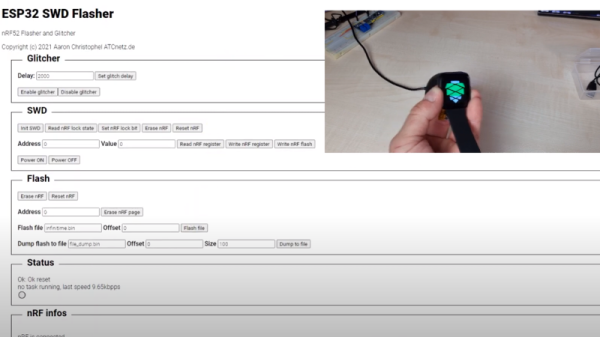
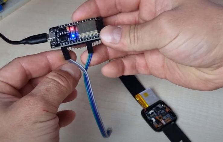 In the first video below [Aaron] demonstrates the technique with the PineTime smartwatch, but the process will be more or less the same regardless of what your target device is. Just connect the CLK and DIO lines to pins GPIO 21 and GPIO 19 of the ESP32, point your web browser to its address on the local network, and you’ll be presented with a straightforward user interface for reading and writing the chip’s flash.
As demonstrated in the second video, with a few more wires and a MOSFET, the ESP32 firmware is also able to perform a power glitch exploit on the chip that will allow you to read the contents of its flash even if the APPROTECT feature has been enabled. [Aaron] isn’t taking any credit for this technique though, pointing instead to the research performed by [LimitedResults] to explain the nuts and bolts of the attack.
We’re always excited when a message from [Aaron] hits the inbox, since more often that not it means another device has received an open source firmware replacement. From his earlier work with cheap fitness trackers to his wildly successful Bluetooth environmental sensor hacking, we don’t think this guy has ever seen a stock firmware that he didn’t want to immediately send to /dev/null.
Continue reading “ESP32 Turned Handy SWD Flasher For NRF52 Chips”