Cybiko Repair-A-Thon With Memory Upgrade

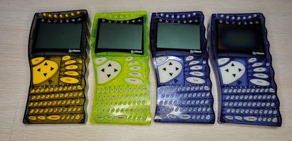
Concluding a four-part repair-a-thon on a stack of Cybiko handheld computers, [Robert] over at Robert’s Retro covered the intricate details of fixing a last batch of four in a nearly one-hour long video. These devices, with their colorful transparent cases, are a great time capsule of the early 2000s. Even with their limited hardware, they provided PDA-like capabilities to teens years before smartphones were a thing, with features including music playback and wireless chat (albeit limited to recipients within 100 meters).

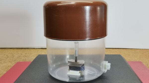
Of the four units covered in this video, they are all the original Cybiko Classic, with two each of the first and second revision, none of which were booting due to a bad Flash chip. Another issue was the dead rumble motors on them, which fortunately are the easiest to replace. One of the units also has a dead display, which did not get replaced this time around.

Insides of a Cybiko Classic (Credit: Robert's Retro, YouTube)
Insides of a Cybiko Classic (Credit: Robert’s Retro, YouTube)

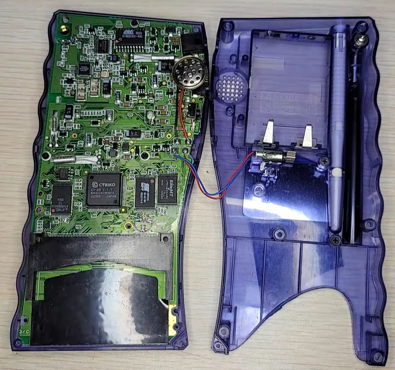
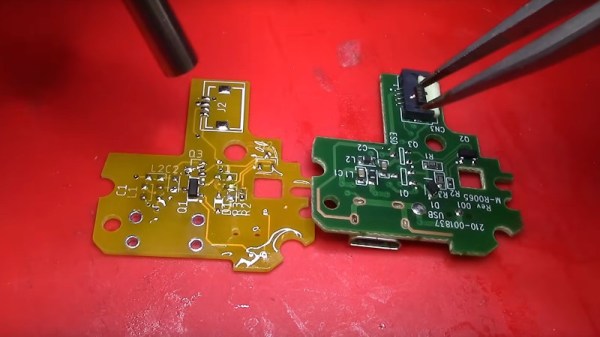
The flash chip replacement was a bit more of a headache, as these devices don’t just take any chip, mostly due to how much the system relies on the ready-busy line. This led [Robert] to replace the old 4 Mb AT45DB041 chips with  the 16 Mb Atmel AT45DB161. Previously he had taken 1 MB chips from an expansion cartridge to replace more dead flash chips, so those were replaced with 2 MB chips.

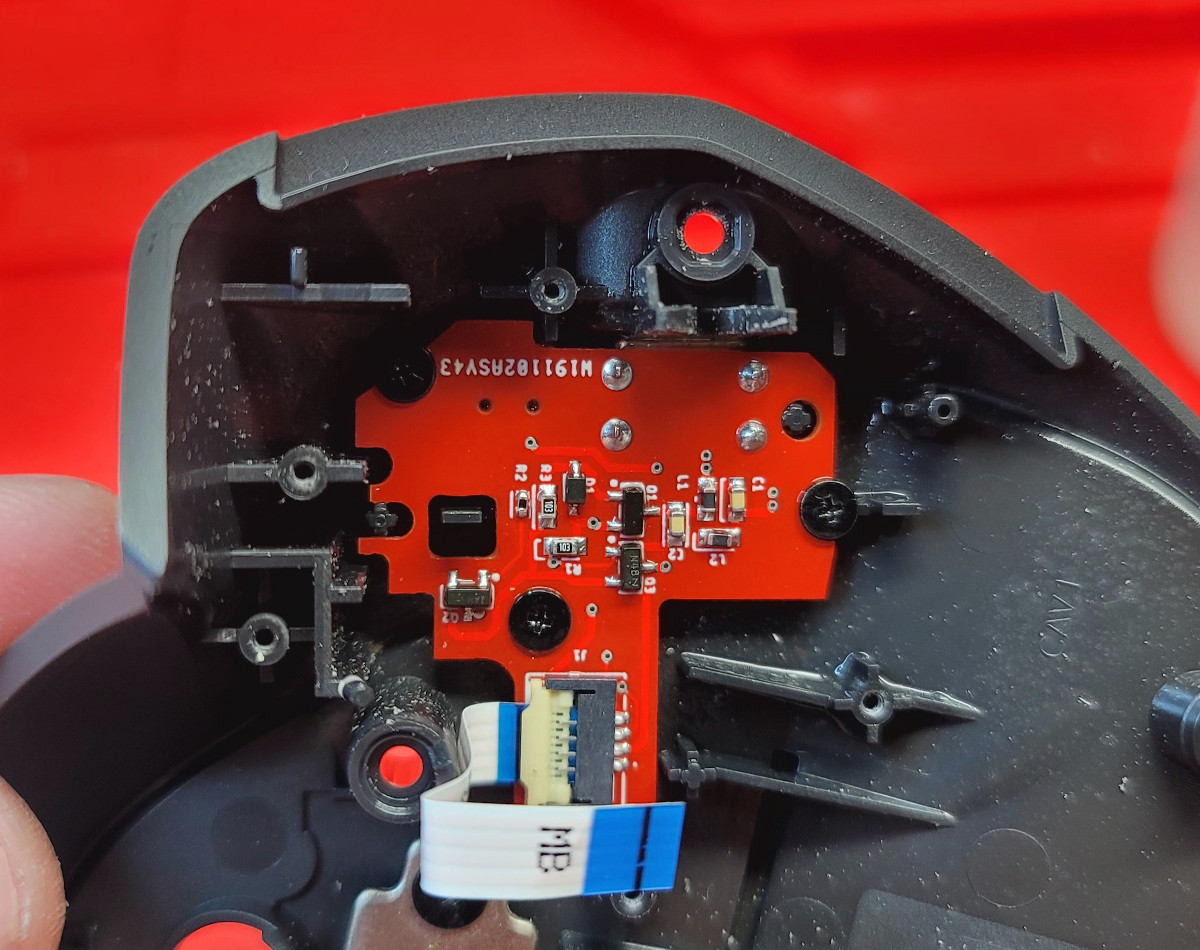
With fresh flash in place, the next challenge was to get these written with a firmware image, with the v2 Cybiko units already having CyOS on the separate 256 kB Flash chip, but the v1 units relying on the single big Flash chip for all storage. Fortunately, an enterprising member of the community developed a tool to ease this ordeal by allowing a Cybiko unit in its serial dock to be flashed with no issues, other than the 2 MB Flash causing some issues as this was a previously unknown hardware configuration.

[Robert] now has four working Cybiko units, with one being headless due to the busted screen, and more room for apps on the 2 MB units than a 2000s teenager would have known what to do with.

Continue reading “Cybiko Repair-A-Thon With Memory Upgrade”

A red hot crucible is held with metal tongs above a white plaster mold. The mold is held in a bright pink silicone sleve atop a metal pan on a wooden workbench. Red cheese wax holds the sleeve to a metal funnel connected to a vacuum cleaner.

Lost Print Vacuum Casting In A Microwave

Hacks are rough around the edges by their nature, so we love it when we get updates from makers about how they’ve improved their process. [Denny] from Shake the Future has just provided an update on his microwave casting process.

Sticking metal in a microwave certainly seems like it would be a bad idea at first, but with the right equipment it can work quite nicely to develop a compact foundry. [Denny] walks us through the process start to finish in this video, including how to build the kilns, what materials to use, and how he made several different investment castings using the process. The video might be worth watching just for all the 3D printed tools he’s built to aid in the process — it’s a great example of useful 3D prints to accompany your fleet of little plastic boats.A hand holds a very detailed copper ring. It is inscribed with the words "Open Source Hardware" and the open gear logo associated with open source hardware. It looks kinda like a class ring.

A lot of the magic happens with a one minute on and six minutes off cycle set by a simple plug timer. This allows a more gradual ramp to burn out the PLA or resin than running the microwave at full blast which can cause some issues with the kiln, although nothing catastrophic as demonstrated. Vacuum is applied to the mold with a silicone sleeve cut from a swimming cap while pouring the molten metal into the mold to draw the metal into the cavities and reduce imperfections.

We appreciate the shout out to respirators while casting or cutting the ceramic fiber mat. Given boric acid’s effects, [PDF] you might want to use safety equipment when handling it as well or just use water as that seems like a valid option.

If you want to see where he started check out this earlier version of the microwave kiln and how he used it to make an aluminum pencil.

Continue reading “Lost Print Vacuum Casting In A Microwave”

Cheap Microscope Can Take Amazing Images With Some Simple Upgrades

[Birdbrain] is trying to make their own microfluidic devices. To aid in this quest, they need a quality microscope to see what they’re doing. Instead of buying one outright, they purchased a cheap microscope and upgraded it to do the job instead.

Usability and performance is greatly improved over the stock unit, which was really only fit for learning purposes.

The cheap education-grade microscope cost around $50 USD, had few features, and wasn’t much chop out of the box. The worst part was the sample stage — which was poorly adjustable in the up-and-down axis and could only track about two centimeters up and down. There was no X or Y axis panning either, and it lacked a proper condensor iris, too. Oh, and the included camera module had a resolution of just 240p.

To fix these problems, the microscope was first outfitted with a fully redesigned X-Y-Z stage built out of old components from a salvaged DVD drive and an additional NEMA stepper motor. Camera-wise, it was hooked up with a 2K Raspberry Pi Camera Module 3 running at 10 to 15 frames per second, which broadcasts video over a local network for easy viewing on an external monitor. It also gained an epi-illumination setup for doing reflected light microscopy.

If you’re eager to build a quality microscope with all the controls you personally dream of, this could be a relevant project for you to study. We’ve featured some other builds along these lines before, too. Video after the break.

Continue reading “Cheap Microscope Can Take Amazing Images With Some Simple Upgrades”

It’s A CoCo! No, It’s An Apple II!

Original retrocomputing hardware is now decades old and showing its age, so the chances are it’s more common in 2024 to experience a machine from the 1970s or 1980s by way of an emulator on a modern machine than it is on the real hardware. There’s another more limited emulation scene as similar 8-bit machines emulate each other, for example when the very similar Dragon 32 and Tandy CoCo have a go at each other’s software. Rarest of them all though is when one classic machine emulates another with a different architecture, but that’s exactly what’s happened with [DragonBytes], who has persuaded a Tandy CoCo to emulate an Apple II.

The two machines have significant hardware differences, but we’re guessing that the project is helped a little by the Motorola 6809 in the CoCo and the MOS 6502 in the Apple having both in a sense been different visions of a successor to the Motorola 6800. Thus their architectures while different, are not diametrically opposed. The other hardware is certainly not so similar though, with Moto’s 6847 display chip in the Tandy being far more conventional than Steve Wozniak’s clever NTSC hacks to achieve a color display for minimal cost on the Apple.

The project is written in assembler, and doesn’t by any means claim to support all Apple modes, or be cycle accurate. But it’s a hugely impressive achievement nevertheless.

The CoCo has an enthusiastic following, and has appeared here a few times in the past. We particularly like this video player.

DIY Geophone Build Performs Well

If you want to know what’s going on with the ground, geologically speaking, a geophone is a great tool to have. It lets you listen in on the rumbles and grumbles beneath your feet, and can give you great insight into matters of seismic importance. [mircemk] has designed a very capable geophone that’s simple enough for you to build at home.

The geophone relies on a mass suspended upon a spring inside a chamber, which as you might imagine, will move when shaken by seismic vibrations. The mass is in fact a plastic rod, fitted with an iron nut and a magnet on the end.

This is mounted above a coil, which is fixed to the base of the chamber. Thus, when the chamber is shaken by seismic activity, the mass moves relative to the coil, with the coil picking up the varying magnetic field as it dances around.

The YouTube video does a great job of explaining the concepts involved and how to practically build the device. [mircemk] has also had some other great projects featured on Hackaday before, too.

Continue reading “DIY Geophone Build Performs Well”

Sometimes It’s The Little Things

I had one of those why-didn’t-I-think-of-it moments this week, reading this article about multiplexing I2C on the ESP32 microcontroller. The idea is so good, and so simple, that it’s almost silly that it’s not standard hacker practice. And above all, it actually helps solve a problem that I’ve got. This is why I read Hackaday every day.

I2C is great in that it lets you connect up multiple devices to a pair of wires using a very bus architecture. Every device has its own address, the host calls them out, and hopefully all other devices keep quiet while just the right one responds. But what happens when you want to use a few of the same sensors, where each IC has the same address? The usual solution is to buy a multiplexer chip.

But many modern microcontrollers, like the ESP32, have an internal multiplexer setup that lets you map the pins with the dedicated hardware peripherals, usually at initialization time. Indeed, I’ve been doing it as an “init” task so long, I never thought to do it otherwise. But that’s exactly the idea behind [BastelBaus]’s hack – if you dynamically reassign the pins, you can do the I2C multiplexing with the chip you’ve got. This should probably work for any other chips that have multiple assignable pins for hardware peripherals as well.

Cool idea, but really simple. Why hadn’t I ever thought of it? I think it’s because I’ve always had this init / mainloop schema in my mind, which for instance the Arduino inherited and formalized in its setup() and loop() functions. Pin mappings go in the init section, right?

So what this hack really amounts to, for me, is a rethinking of what’s static and what’s dynamic. It’s always worth questioning your assumptions, especially when you’re facing a problem that requires a creative solution. Sometimes limitations are only in your mind. Have you had your mind opened recently by a tiny little hack?

Designing A USB-C Upgrade PCB For The MX Ergo Mouse

As the world of electronic gadgetry made the switch from micro USB to USB-C as the charging port of choice, many of us kept both of the required cables handy. But it’s fair to say that these days a micro USB port has become a pretty rare sight, and the once ubiquitous cable can be a bit elusive in the event that you encounter an older device that requires it.

[Solderking] has a high-end Logitech cordless mouse with just this problem, and so he replaced its micro USB socket with a USB-C port. That makes the task sound deceptively simple, because in fact he had to reverse engineer one of the device’s PCBs in its entirety, making a new board with the same outline and components, but sporting the new connector.

Instead of attempting to replicate the complex shape with geometry he started with a scan of the board and had Fusion 360 trace its outline before 3D printing a version of it to check fit in the Logitech case. Then it was a case of tracing the circuit, designing the replacement, and hand transferring the parts from board to board.

The result is a USB-C chargeable mouse, and while all the design files don’t appear to be online, it’s possible to download the Gerbers from a PCBWay page. On top of that there’s a YouTube video of the process which we’ve placed below the break.

This isn’t the first time we’ve seen somebody spin up a new board to add USB-C to an older device — this drop-in replacement for Sony’s DualShock 4 comes to mind. If you’ve got enough free space inside your particular gadget, you might be able to pull of a USB-C conversion with nothing more exotic than a hacked up Adafruit breakout board.

Continue reading “Designing A USB-C Upgrade PCB For The MX Ergo Mouse”