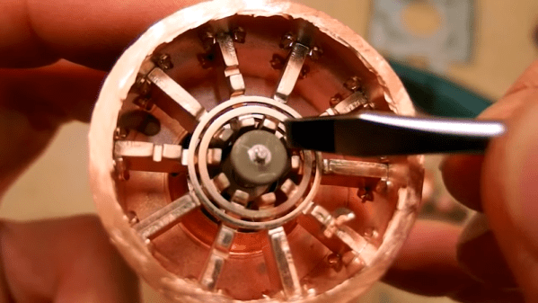
Fair warning: any homeowners who have thermostats similar to the one that nearly burned down [Kerry Wong]’s house might be in store for a sleepless night or two, at least until they inspect and perhaps replace any units that are even remotely as sketchy as what he found when he did the postmortem analysis in the brief video below.
The story begins back in the 1980s, when the Southern New England area where [Kerry] lives enjoyed a housing boom. Contractors rushed to turn rural farmland into subdivisions, and new suburbs crawled across the landscape. Corners were inevitably cut during construction, and one common place to save money was the home’s heating system. Rather than engage an HVAC subcontractor to install a complicated heating system, many builders opted instead to have the electricians install electric baseboards. They were already on the job anyway, and at the time, both copper and electricity were cheap.
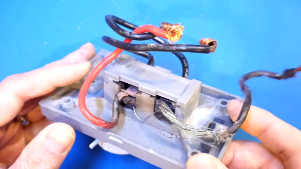
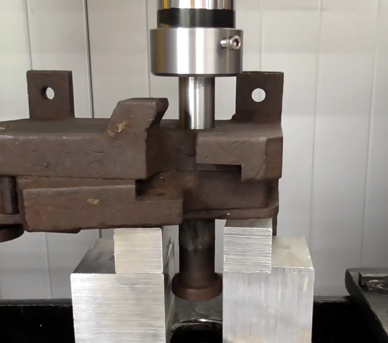
Fast forward 40 years or so, and [Kerry] finds himself living in one such house. The other night, upon catching the acrid scent of burning insulation, he followed his nose to the source: a wall-mounted thermostat for his electric baseboard. His teardown revealed burned insulation, bare conductors, and scorched plastic on the not-so-old unit; bearing a 2008 date code, the thermostat must have replaced one of the originals. [Kerry] poked at the nearly combusted unit and found the root cause: the spot welds holding the wires to the thermostat terminal had become loose, increasing the resistance of the connection. As [Kerry] points out, even a tenth of an ohm increase in resistance in a 15 amp circuit would dissipate 20 watts of heat, and from the toasty look of the thermostat it had been a lot more than that.
The corner-cutting of the 1980s was nothing new, of course – remember the aluminum wiring debacle? Electrical fires are no joke, and we’re glad [Kerry] was quick to locate the problem and prevent it from spreading.
Continue reading “Fail Of The Week: Thermostat Almost Causes A House Fire”
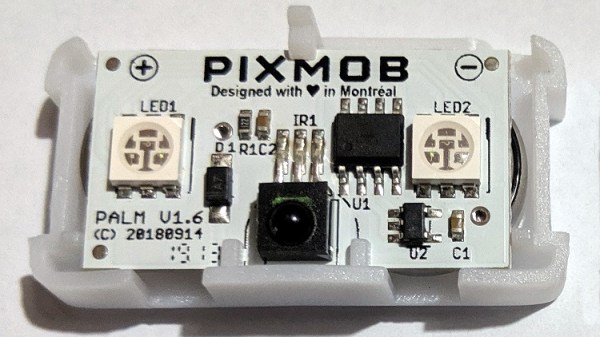
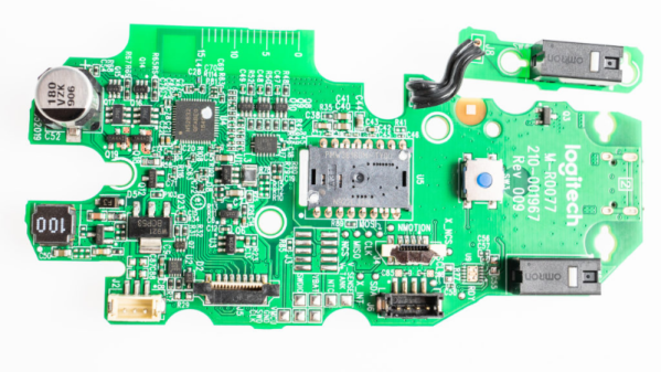
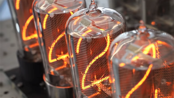
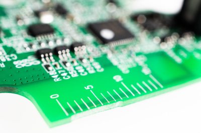 [Eric] points out several incremental changes in design which have resulted in improved ergonomics. He also uncovers a few nuggets of useful information. The use of interchangeable mold inserts help make molds last longer while still offering the flexibility to make changes in the molded part. It’s interesting to see special components being used for withstanding vibration and high-G forces. Some of these insights can be useful for those moving from prototyping to production. There’s one puzzling feature on the new PCB that [Eric] cannot figure out. There is a 15 mm scale screen-printed over the blue tooth antenna. If you have an answer on its purpose, let us know in the comments below.