Recreating The Analog Beauty Of A Vintage Tektronix Oscillator

Tektronix must have been quite a place to work back in the 1980s. The company offered a bewildering selection of test equipment, and while the digital age was creeping in, much of their gear was still firmly rooted in the analog world. And some of the engineering tricks the Tek wizards pulled off are still the stuff of legend.

One such gem of analog design was the SG505, an ultra-low-distortion oscillator module that [Paul] is trying to replicate with modern parts. That’s a tall order since not only did the original specs on this oscillator call for less than 0.0008% total harmonic distortion over a frequency range of 20 Hz to 20 kHz, but a lot of the components it used are no longer manufactured. Tek also tended to use a lot of custom parts, especially mechanical ones like the barrel switch used to select attenuation levels in the SG505, leaving [Paul] no choice but to engineer his way around them.

So far, [Paul] has managed to track down most of the critical components or source suitable substitutes. One major win was locating the original J-FET Tek used in the oscillator’s AGC circuit. One part that’s proven more elusive is the potentiometer that Tek used to adjust the frequency; who knew that finding a dual-gang precision wirewound 10k single-turn pot with no physical stop would be such a chore?

[Paul] still seems to be very much in the planning stages of this project yet, and that’s probably for the best since projects such as these live and die on proper planning. We’re keen to see how this develops, and we’re very much looking forward to seeing the FFT results. We also imagine he’ll be busting out his custom curve tracer at some point in the build, too.

Retrotechtacular: Soldering The Tek Way

For a lot of us, soldering just seems to come naturally. But if we’re being honest, none of us was born with a soldering iron in our hand — ouch! — and if we’re good at soldering now, it’s only thanks to good habits and long practice. But what if you’re a company that lives and dies by the quality of the solder joints your employees produce? How do you get them to embrace the dark art of soldering?

If you’re Tektronix in the late 1970s and early 1980s, the answer is simple: make in-depth training videos that teach people to solder the Tek way. The first video below, from 1977, is aimed at workers on the assembly line and as such concentrates mainly on the practical aspects of making solid solder joints on PCBs and mainly with through-hole components. The video does have a bit of theory on soldering chemistry and the difference between eutectic alloys and other tin-lead mixes, as well as a little about the proper use of silver-bearing solders. But most of the time is spent discussing the primary tool of the trade: the iron. Even though the film is dated and looks like a multi-generation dupe from VHS, it still has a lot of valuable tips; we’ve been soldering for decades and somehow never realized that cleaning a tip on a wet sponge is so effective because the sudden temperature change helps release oxides and burned flux. The more you know.

The second video below is aimed more at the Tek repair and rework technicians. It reiterates a lot of the material from the first video, but then veers off into repair-specific topics, like effective desoldering. Pro tip: Don’t use the “Heat and Shake” method of desoldering, and wear those safety glasses. There’s also a lot of detail on how to avoid damaging the PCB during repairs, and how to fix them if you do manage to lift a trace. They put a fair amount of emphasis on the importance of making repairs look good, especially with bodge wires, which should be placed on the back of the board so they’re not so obvious. It makes sense; Tek boards from the era are works of art, and you don’t want to mess with that.

Continue reading “Retrotechtacular: Soldering The Tek Way”

Close Shave For An Old Oscilloscope Saved With A Sticky Note

When you tear into an old piece of test equipment, you’re probably going to come up against some surprises. That’s especially true of high-precision gear like oscilloscopes from the time before ASICs and ADCs, which had to accomplish so much with discrete components and a lot of engineering ingenuity.

Unfortunately, though, those clever hacks that made everything work sometimes come back to bite you, as [Void Electronics] learned while bringing this classic Tektronix 466 scope back to life. A previous video revealed that the “Works fine, powers up” eBay listing for this scope wasn’t entirely accurate, as it was DOA. That ended up being a bad op-amp in the power supply, which was easily fixed. Once powered up, though, another, more insidious problem cropped up with the vertical attenuator, which failed with any setting divisible by two.

With this curious symptom in mind, [Void] got to work on the scope. Old analog Tek scopes like this use a bank of attenuator modules switched in and out of the signal path by a complex mechanical system of cams. It seemed like one of the modules, specifically the 4x attenuator, was the culprit. [Void] did the obvious first test and compared the module against the known good 4x module in the other channel of the dual-channel scope, but surprisingly, the module worked fine. That meant the problem had to be on the PCB that the module lives on. Close examination with the help of some magnification revealed the culprit — tin whiskers had formed, stretching out from a pad to chassis ground. The tiny metal threads were shorting the signal to ground whenever the 4x module was switched into the signal path. The solution? A quick flick with a sticky note to remove the whiskers!

This was a great fix and a fantastic lesson in looking past the obvious and being observant. It puts us in the mood for breaking out our old Tek scope and seeing what wonders — and challenges — it holds.

Continue reading “Close Shave For An Old Oscilloscope Saved With A Sticky Note”

Hackaday Links Column Banner

Hackaday Links: September 1, 2024

Why is it always a helium leak? It seems whenever there’s a scrubbed launch or a narrowly averted disaster, space exploration just can’t get past the problems of helium plumbing. We’ve had a bunch of helium problems lately, most famously with the leaks in Starliner’s thruster system that have prevented astronauts Butch Wilmore and Suni Williams from returning to Earth in the spacecraft, leaving them on an extended mission to the ISS. Ironically, the launch itself was troubled by a helium leak before the rocket ever left the ground. More recently, the Polaris Dawn mission, which is supposed to feature the first spacewalk by a private crew, was scrubbed by SpaceX due to a helium leak on the launch tower. And to round out the helium woes, we now have news that the Peregrine mission, which was supposed to carry the first commercial lander to the lunar surface but instead ended up burning up in the atmosphere and crashing into the Pacific, failed due to — you guessed it — a helium leak.
Continue reading “Hackaday Links: September 1, 2024”

TDS 744A Scope Teardown Fixes Dodgy Channel

There are a lot of oscilloscopes from around the 1990s which are still very much desirable today, such as the Tektronix TDS 744A which [DiodesGoneWild] got his grubby mitts on. This is a 500 MHz, 4-channel scope, with a capture rate of 500 MS/s (4 channels) to 2 GS/s (1 channel). It also has a color display and even comes with a high-density (1.44 MB) floppy drive. Unfortunately this particular unit was having trouble with its fourth channel, and its NuColor display had degraded, something that’s all too common with this type of hybrid CRT/LCD (LCCS) technology.

Starting with a teardown of the unit to inspect the guts, there was no obvious damage on the PCBs, nor on the acquisition board which would explain the weird DC offset on the fourth channel. After cleaning and inspecting the capture module and putting the unit back together, the bias seen on channel four seemed to disappear. A reminder that the best problems are the ones that solve themselves. As for the NuColor display, this uses a monochrome CRT (which works fine) and an LCD with color filters. It’s the latter which seems degraded on this unit, with a repair still being planned.

We covered NuColor-based devices before, which offer super-sharp details that are hard to capture even with modern-day LCDs, never mind the ones of the 90s. Fixing these NuColor displays can be easy-ish sometimes, as [JVG] found when tearing apart a very similar Tektronix TDX-524A which required a power supply fix and the removal of goopy gel between the CRT and LCD to restore it.

Continue reading “TDS 744A Scope Teardown Fixes Dodgy Channel”

Tektronix’s Ceramic CRT Production And The Building 13 Catacombs

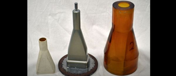
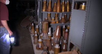
As a manufacturer of test equipment and more, Tektronix has long had a need for custom form factors with its CRT displays. They initially went with fully glass CRTs as this was what the booming television industry was also using, but as demand for the glass component of CRTs increased, so did the delays in getting these custom glass components made. This is where Tektronix decided to use its existing expertise with ceramic strips during the pre-PCB era to create ceramic funnels for ceramic CRTs, as described in this 1967 video.

The Tektronix ceramic CRT molds underneath Building 13.

Recently, underneath Building 13 at the Tektronix campus, a ‘catacomb’ full of the molds for these funnels was discovered, covering a wide range of CRT types, including some round ones that were presumably made for military purposes, such as radar installations. These molds consist out of an inner part  (the mandrel) made from 7075-T6 aluminium, and an outer cast polyurethane boot. The ceramic (forsterite) powder is then formed under high pressure into the ceramic funnel, which is then fired in a kiln before a full inspection and assembly into a full CRT, including the phosphor-coated glass front section and rear section with the electron guns.

The advantages of ceramic funnels over glass ones are many, including the former being much harder and resilient to impact forces, while offering a lot of strength for thinner, lighter structures, all of which is desirable in (portable) lab equipment. Although LCDs would inevitably take over from CRTs here as well, these ceramic CRTs formed an integral part of Tektronix’s products, with every part of production handled in-house.

Continue reading “Tektronix’s Ceramic CRT Production And The Building 13 Catacombs”

Inside A Current Probe

[The Signal Path] had two Tektronix AC/DC current probes that didn’t work. Of course, that’s a great excuse to tear them open and try to get at least one working. You can see how it went in the video below. The symptoms differed between the two units, and along the way, the theory behind these probes needs some exploration.

The basic idea is simple, but, of course, the devil is in the details. A simple transformer doesn’t work well at high frequencies and won’t work at all at DC. The solution is to use a hall effect sensor to measure DC and also to feed it back to cancel coil saturation.

Continue reading “Inside A Current Probe”