Now that the Apple wristwatch is on its way, some people are clamoring with excitement and anticipation. Rather than wait around for the commercial product, Instructables user [Aleator777] decided to build his own wearable Apple watch. His is a bit different though. Rather than look sleek with all kinds of modern features, he decided to build a watch based on the 37-year-old Apple II.
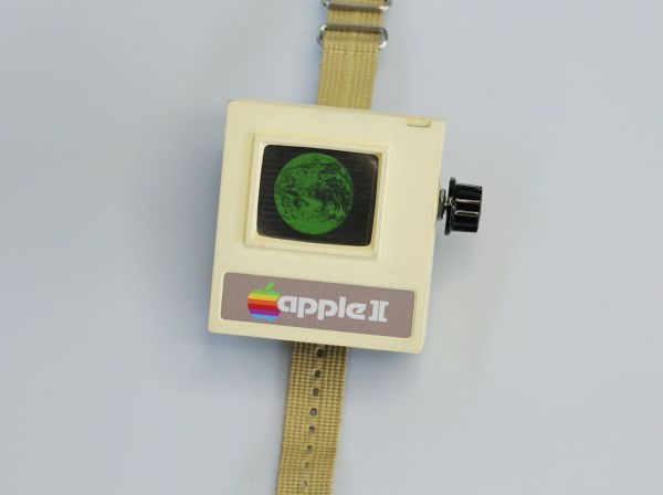
The most obvious thing you’ll notice about this creation is the case. It really does look like something that would have been created in the 70’s or 80’s. The rectangular shape combined with the faded beige plastic case really sells the vintage electronic look. It’s only missing wood paneling. The case also includes the old rainbow-colored Apple logo and a huge (by today’s standards) control knob on the side. The case was designed on a computer and 3D printed. The .stl files are available in the Instructable.
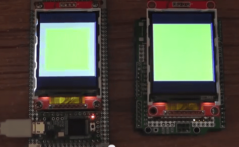
This watch runs on a Teensy 3.1, so it’s a bit faster than its 1977 counterpart. The screen is a 1.8″ TFT LCD display that appears to only be using the color green. This gives the vintage monochromatic look and really sells the 70’s vibe. There is also a SOMO II sound module and speaker to allow audio feedback. The watch does tell time but unfortunately does not run BASIC. The project is open source though, so if you’re up to the challenge then by all means add some more functionality.
As silly as this project is, it really helps to show how far technology has come since the Apple II. In 1977 a wristwatch like this one would have been the stuff of science fiction. In 2015 a single person can build this at their kitchen table using parts ordered from the Internet and a 3D printer. We can’t wait to see what kinds of things people will be making in another 35 years.