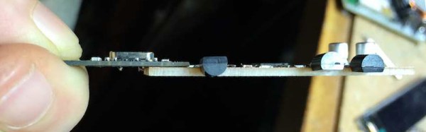
In our last installment of Tools of the Trade, we had just finished doing the inspection of the surface mount part of the PCB. Next in the process is the through hole components. Depending on the PCB, the order may change slightly, but generally it makes more sense to get all the SMT work done before moving to the through hole work.
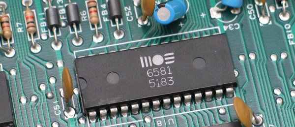
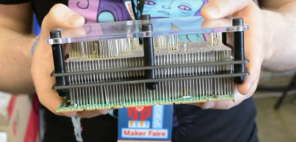
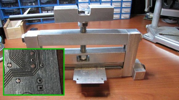
Through hole used to be the standard, but as the need for size reduction and automation increased, SMT gained favor. However, there are still a lot of reasons to use through hole components, so they aren’t going away entirely (at least not any time soon). One of the biggest advantages of THT is mechanical strength, which makes it better suited for connectors than SMT. If you’ve ever popped a microusb connector off a PCB by breathing on it heavily, you’ll understand. So, how do we most efficiently get through hole components on a PCB, and how do the big boys do it?
Continue reading “Tools Of The Trade – Through Hole Assembly” →