Funny stuff, electricity. It’s all about the volts and the amps, and controlling these two factors. Most of the time, the electricity coming into your device is at a higher voltage than you need, so you have to convert it down to something more usable. The easiest way to do this is with a transformer.
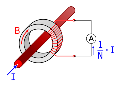
The transformer in your power supply takes a high voltage from the mains and converts it down into a lower voltage to power your gadgets. You’ll find one in all power supplies, from the miniature USB version that powers your cell phone to the big ones hanging on a telephone pole that drive your home’s mains electricity. Although these transformers are different sizes, they share the same fundamental design.


