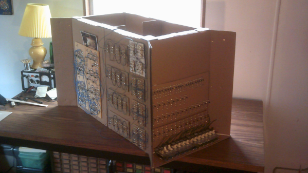
Every time we say “We’ve seen it all”, along comes a project that knocks us off. 60 year old [Mark Nesselhaus] likes to learn new things and he’s never worked with hardware at the gate level. So he’s building himself a 4-bit Computer, using only Diode-Transistor Logic. He’s assembling the whole thing on “card board” perf-board, with brass tacks for pads. Why — because he’s a thrifty guy who wants to use what he has lying around. Obviously, he’s got an endless supply of cardboard, tacks and Patience. The story sounds familiar. It started out as a simple 4-bit full adder project and then things got out of hand. You know he’s old school when he calls his multimeter an “analog VOM”!
It’s still work in progress, but he’s made a lot of it in the past year. [Mark] started off by emulating the 4-bit full adder featured on Simon Inns’ Waiting for Friday blog. This is the ALU around which the rest of his project is built. With the ALU done, he decided to keep going and next built a 4-to-16 line decoder — check out the thumbnail image to see the rats nest of jumbled wires. Next on his list were several flip flops — R-S, J-K and D types, which would be useful as program counters. This is when he bumped into problems with signal levels, timing and triggering. He decided to allow himself the luxury of adding one IC to his build — a 555 based clock generator. But he still needed some pulse shaping circuitry to make it work consistently.
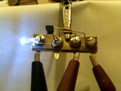
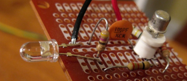
[Mark] also built a finite-state-machine sequencer based on the work done by Rory Mangles TinyTim project. He finished building some multiplexers and demultiplexers, and it appears he may be using a whole bank of 14 wall switches for address, input and control functions. For the output display, he assembled a panel using LED’s recovered from a $1 Christmas light string. Something seems amiss with his LED driver, though — 2mA with LED on and >2.5mA with LED off. The LED appears to be connected across the collector and emitter of the PNP transistor. Chime in with your comments.
This build seems to be shaping along the lines of the Megaprocessor that we’ve swooned over a couple of times in the past. Keep at it, [Mark]!