Hi-Fi Combines Best Of 60s And 90s Technology

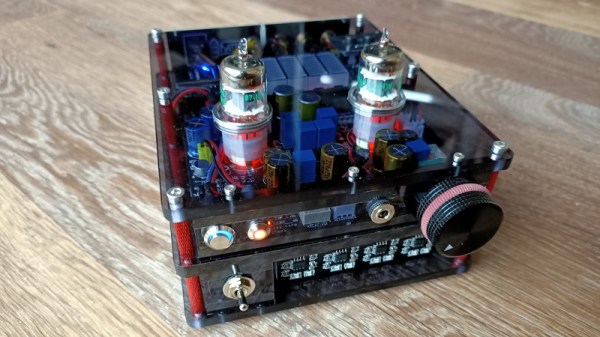
The 90s were a dark time for audio equipment, literally and figuratively. Essentially the only redeeming quality from the decade of nondescript black plastic boxes was the low cost. Compared to the audio equipment of the 60s, largely produced in high-end enclosures with highly desirable tube amplifiers, the 90s did not offer much when it came to hi-fi stereo sound. However, those cheap black boxes from the 90s turn out to be surprisingly perfect for project enclosures for other amplifier builds, such as this 60s-era tube amp recreation.

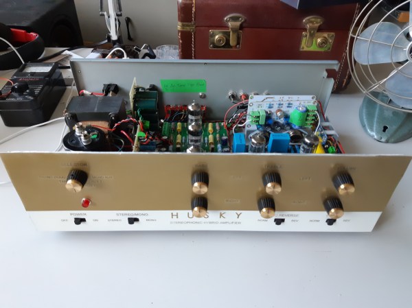
This mesh of the best of two distinct decades comes from [Alvenh] and begins by preparing the old enclosure for its new purpose. This means a lot of work fabricating a custom metal face plate for the new amplifier and significantly modifying the remaining case. After the box is complete, the amplifier build began. It uses a tube-based preamp and a solid-state power amplifier since [Alvenh]’s experience suggested that the warm tube sound was generated mostly in the preamp. This means that his design is a hybrid but still preserves the essential qualities of a full tube build.

The build also includes a radio module that has the ability to cover the 2m and 70cm bands popular in ham radio. This module also has been found to have much better audio quality than the standard AM/FM receiver typically used in projects like this. With the radio module added to the custom enclosure, as well as a phono amp and a power supply, [Alvenh] has an excellent audio amplifier in an inexpensive case which preserves the tube sound from the true hi-fi eras of decades past.

Continue reading “Hi-Fi Combines Best Of 60s And 90s Technology”

A Tiny Tube Amp For Not A Lot

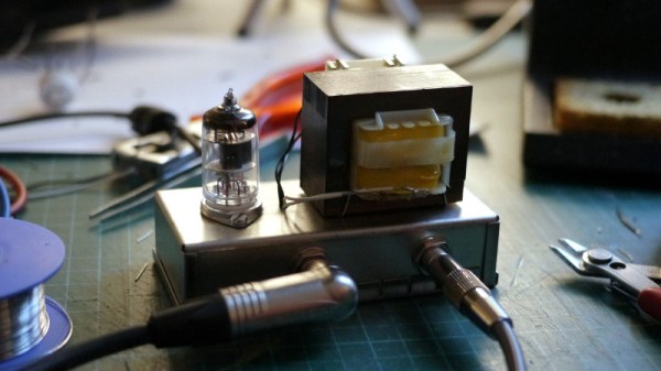
At the extreme budget end of tube audio lie single-tube amplifiers usually using very cheap small-signal pentodes. They’ve appeared here before in various guises, and a fitting addition to those previous projects comes from [Kris Slyka]. It’s a classic circuit with a transformer output, and it provides enough amplification to drive a pair of headphones or even a speaker at low levels.

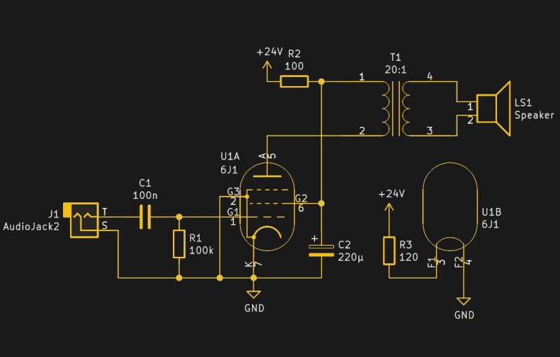
The fairly conventional circuit of the tube amplifier.

Most tube enthusiasts will instantly recognize the anode follower circuit with a transformer in the anode feed through which the output is taken. The tube works in Class A, which means that it’s in its least efficient mode but the one with the least distortion. The transformer itself isn’t an audio part, but a small mains transformer taken from a scrap wall wart. It serves not only for isolation, but also to transform the high impedance output from the tube into a low impedance suitable for driving a headphone or speaker.

The HT voltage is a relatively low 24 V, but it still manages to drive headphones acceptably. Speaker levels require a pre-amp, but even then it’s likely that this circuit is pushing the tube beyond what it’s capable of with a speaker. The more it operates towards the edge of its performance envelope the more distortion it will generate and the worse a sound it will produce. This isn’t such a problem in a guitar application as here, but hi-fi enthusiasts may find it to be too much. It would be interesting to subject it as a headphone amplifier to a series of audio tests to evaluate the effect of a mains transformer over a dedicated audio one.

Last year we took a very in-depth look at the commonly-available Chinese kit pre-amps that use a similar anode-follower circuit but without the transformer. We’ve also seen a similar amp that uses an op-amp as an impedance converter, as well as a novel take on the idea whose unusual biasing allows it to run from only 3.3 volts. These circuits can be so cheap to get started with that we’d suggest anyone give them a try.

A Very Modern Tube Headphone Amplifier

Once a discarded relic, over the years the humble vacuum tube has been rehabilitated in the arena of specialist audio. There are plenty of tube amplifiers now being manufactured, with a popular choice being headphone amplifiers that use a tube as a gain stage followed by an op-amp as a buffer with a low impedance output. This forms the basis of [Ratti3]’s amplifier, but with the added interest of a battery supply and a Bluetooth connection.

The tube circuit is a very conventional anode follower using an EF95 pentode. This provides plenty of gain and of course that “valve sound” beloved of audio enthusiasts, but suffers from an output impedance too high to drive a set of headphones. An NE5532 steps in for the op-amp buffer role, making for a very simple circuit. Power comes from a set of four 18650 Lithium-Ion cells with associated charger and balance boards, while a little switching boost converter provides the 100 volt HT for the tubes.

We’ve visited this type of amplifier before with a similar but much more rough-around-the-edges Chinese version. That had some astonishingly cheap Chinese tubes, but if we’re seeking better components it’s interesting to know just who makes tubes these days.

Meet The Magic Eye Vacuum Tube

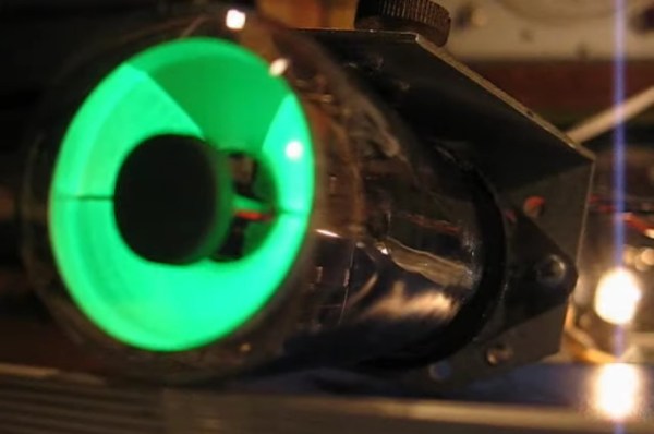
Vacuum tubes ruled electronics for several decades and while you might think of them as simple devices analogous to a transistor or FET, there were many special types. We’re all familiar with nixie tubes that act as numeric displays, and there are other specialty tubes that work as a photomultiplier, to detect radiation, or even generate microwaves. But one of the most peculiar and distinctive specialty tubes has an intriguing name: a magic eye tube. When viewed from the top, you see a visual indication that rotates around a central point, the out ring glowing while the inner is dark, like an iris and pupil.

By [Quark48] – CC BY-SA 2.0

These tubes date back to the RCA 6E5 in 1935. At the time, test equipment that used needles was expensive to make, so there was always a push to replace them with something cheaper.  They were something like a stunted cathode ray tube. In fact, the inventor, Allen DuMont, was well known for innovations in television. An anode held a coating that would glow when hit with electrons — usually green, but sometimes other colors. Later tubes would show a stripe going up and down the tube instead of a circle, but you still call them magic eyes.

The indicator part of this virtual meter took the form of a shadow. Based on the applied signal, the shadow would be larger or smaller. Many tubes also contained a triode which would drive the tube from a signal.

There’s a great web site full of information on these venerable tubes and it has examples of these tubes appearing in plenty of things. They frequently appeared in service equipment, radios, and tape recorders. They even appeared in pro audio equipment like the Binson Echorec echo-delay unit.

Continue reading “Meet The Magic Eye Vacuum Tube”

Vacuum Tube Logic Hack Chat

Join us on Wednesday, December 9th at noon Pacific for the Vacuum Tube Logic Hack Chat with David Lovett!

For most of us, circuits based on vacuum tubes are remnants of a technological history that is rapidly fading from our collective memory. To be sure, there are still applications for thermionic emission, especially in power electronics and specialized switching applications. But by and large, progress has left vacuum tubes in a cloud of silicon dust, leaving mainly audiophiles and antique radio enthusiasts to figure out the hows and whys of plates and grids and filaments.

But vacuum tubes aren’t just for the analog world. Some folks like making tubes do tricks they haven’t had to do in a long, long time, at least since the birth of the computer age. Vacuum tube digital electronics seems like a contradiction in terms, but David Lovett, aka Usagi Electric on YouTube, has fallen for it in a big way. His channel is dedicated to working through the analog building blocks of digital logic circuits using tubes almost exclusively. He has come up with unique circuits that don’t require the high bias voltages typically needed, making the circuits easy to work with using equipment likely to be found in any solid-state experimenter’s lab.

David will drop by the Hack Chat to share his enthusiasm for vacuum tube logic and his tips for exploring the sometimes strange world of flying electrons. Join us as we discuss how to set up your own vacuum tube experiments, learn what thermionic emission can teach us about solid-state electronics, and maybe even get a glimpse of what lies ahead in his lab.

join-hack-chatOur Hack Chats are live community events in the Hackaday.io Hack Chat group messaging. This week we’ll be sitting down on Wednesday, December 9 at 12:00 PM Pacific time. If time zones have you tied up, we have a handy time zone converter.

Click that speech bubble to the right, and you’ll be taken directly to the Hack Chat group on Hackaday.io. You don’t have to wait until Wednesday; join whenever you want and you can see what the community is talking about.

Continue reading “Vacuum Tube Logic Hack Chat”

That Elusive Valve Amp Sound, For Not A Lot! (There Has To Be A Catch)

It was with considerable interest last month that I set out to track down where in the world there are still factories making tubes. My research found them in Slovakia, Russia, and China, and it’s fairly certain I didn’t find all the manufacturers by any means. There appeared to be a whole class of mundane tubes still in production that weren’t to be found on their glossy websites. A glance at any outlet through which Chinese modules can be bought will find this type of tube in small audio amplifier projects, and some of them can be astoundingly cheap. When faced with cheap electronics of course I’m tempted to buy some, so I parted with about £10 ($12.50) and bought myself a kit for a two-tube device described as a stereo preamplifier and headphone amplifier.

An Unusual Tube Choice For Audio

What I received for my tenner was a press-seal bag with a PCB and a pile of components, and not much else. No instructions, which would have been worrisome were the board not clearly marked with the value of each component. The circuit was on the vendor’s website and is so commonly used for these sort of kits that it can be found all over the web — a very conventional twin common-cathode amplifier using a pair of 6J1 miniature pentodes, and powered through a +25 V and -25 V supply derived from a 12 VAC input via a voltage multiplier and regulator circuit. It has a volume potentiometer, two sets of phono sockets for input and output, and the slightly naff addition of a blue LED beneath each tube socket to impart a blue glow. I think I’ll pass on that component.

The 6J1 seems to be ubiquitous throughout the Chinese kits, which is surprising when you understand that it’s not an audio tube at all. Instead it’s a small-signal VHF amplifier, a rough equivalent of the European EF95, and would be much more at home in an FM radio receiver or turret TV tuner from the 1950s. I can only assume that somewhere in China there’s a tube factory tooled up for radio tube production that is targeting this market, because another tube you will see in audio power amplifier kits is the FU32 or QQV03-20 in European parlance, a large power beam tetrode that might have been found in a 1950s military radio transmitter. Still just as if you were to use an RF transistor in an audio circuit it would give good account of itself, so it is with an RF tube. There is no reason a 6J1 won’t do an acceptable job in a circuit such as this one.

Continue reading “That Elusive Valve Amp Sound, For Not A Lot! (There Has To Be A Catch)”

Live Map Of London Tube Created In PCB And Lights

If you’re a frequent traveler on a public transit system, it can be helpful to know when the trains or buses are arriving and if there are any delays. We might reach for a tablet to mount on the wall, but that relies on keeping the OS, the software, and its library dependancies up to date. For true reliability you’ll need to build directly in hardware, which is exactly what this map of the London tube system uses.

The base map is printed directly on PCB, with LEDs along each of the major routes to indicate the current location of the trains. A few small chips handle the WiFi connection — it appears to our eye to be an ESP8266 — and pulling the information about the trains from the London Underground API (it would be virtually impossible to build everything for this project in hardware). The hardware can be easily reprogrammed, and with the PCB layout this could be adapted for other public transit fairly easily.

Even apart from the philosophical differences on design between hardware and software approaches, we still appreciate the aesthetic of LEDs on PCB. In fact, we’ve seen a whole host of artwork on PCBs ever since the price came down dramatically in the past two decades.

Thanks to [Al] for the tip!