Assess Your Output With A Cheap DIY Urine Flowmeter

Some things about the human body are trivial to measure. Height, weight, blood pressure, pulse, temperature — these are all easily quantifiable with the simplest of instruments and can provide valuable insights into our state of health. Electrical activity in the heart and the brain can be captured with more complex instruments, too, and all manner of scopes can be inserted into various orifices to obtain actionable information about what’s going on.

But what about, err, going? Urine flow can be an important leading indicator for a host of diseases and conditions, but it generally relies on subjective reports from the patient. Is there a way to objectively measure how well urine is flowing? Of course there is.

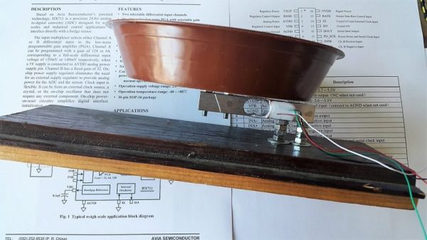
The goal for [GreenEyedExplorer]’s simple uroflowmeter is simple: provide a cheap, easy to use instrument that any patient can use to quantify the rate of urine flow while voiding. Now, we know what you’re thinking — isn’t liquid flow usually measured in a closed system with a paddlewheel or something extending into the stream? Wouldn’t such a device for urine flow either be invasive or messy, or both? Rest assured, this technique is simple and tidy. A small load cell is attached to an ESP8266 through an HX711 load cell amp. A small pan on the load cell receives urine while voiding, and the force of the urine striking the pan is assessed by the software. Reports can be printed to share with your doctor, and records are kept to see how flow changes over time.

All kidding aside, this could be an important diagnostic tool, and at 10€ to build, it empowers anyone to take charge of their health. And since [GreenEyedExplorer] is actually a urologist, we’re taking this one seriously.

Continue reading “Assess Your Output With A Cheap DIY Urine Flowmeter”

Hackaday Prize Entry: OrthoSense, A Smart Knee Brace For Physical Therapy

If you have knee surgery, you can probably count on some physical therapy to go with it. But one thing you might not be able to count on is getting enough attention from your therapist. This was the case with [Vignesh]’s mother, who suffers from osteoarthritis (OA). Her physiotherapist kept a busy schedule and couldn’t see her very often, leaving her to wonder at her rehabilitation progress.

[Vignesh] already had a longstanding interest in bio-engineering and wearables. His mother’s experience led him down a rabbit hole of research about the particulars of OA rehabilitation. He found that less than 35% of patients adhere to the home regimen they were given. While there are a lot of factors at play, the lack of feedback and reinforcement are key components. [Vignesh] sought to develop a simple system for patients and therapists to share information.

The fruit of this labor is Orthosense, an intelligent knee brace system that measures gait angle, joint acoustics, and joint strain.  The user puts on the brace, pairs it with a device, and goes through their therapy routine. Sensors embedded in the brace upload their data to the cloud over Bluetooth.

Joint strain is measured by a narrow strip of conductive fabric running down the length of the knee. As the user does their exercises, the fabric stretches and relaxes, changing resistances all the while. The changes are measured against a Wheatstone bridge voltage divider. The knee’s gait angle is measured with an IMU and is calculated relative to the hip angle—this gives a reference point for the data collected by the strain sensor. An electret mic and a sensitive contact mic built for body sounds picks up all the pops and squeaks emitted by the knee. Analysis of this data provides insight into the condition of the cartilage and bones that make up the joint. As you might imagine, unhealthy cartilage is noisier than healthy cartilage.

[Vignesh]’s prototype is based the tinyTILE because of the onboard IMU, ADC, and Bluetooth. Since all things Curie are being discontinued, the next version will either use something nRF52832 or a BC127 module and a la carte sensors. [Vignesh] envisions a lot for this system, and we are nodding our heads to all of it.

Crossing Wheatstone Bridges

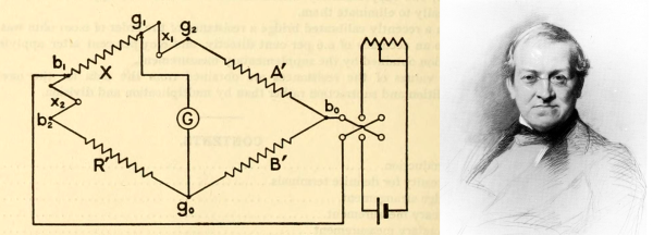
The Wheatstone bridge is a way of measuring resistance with great accuracy and despite having been invented over 150 years ago, it still finds plenty of use today. Even searching for it on Hackaday brings up its use in a number of hacks. It’s a fundamental experimental device, and you should know about it.

Continue reading “Crossing Wheatstone Bridges”

Automatic Resistance: Resistors Controlled By The Environment

Resistors are one of the fundamental components used in electronic circuits. They do one thing: resist the flow of electrical current. There is more than one way to skin a cat, and there is more than one way for a resistor to work. In previous articles I talked about fixed value resistors as well as variable resistors.

There is one other major group of variable resistors which I didn’t get into: resistors which change value without human intervention. These change by environmental means: temperature, voltage, light, magnetic fields and physical strain. They’re commonly used for automation and without them our lives would be very different.

Continue reading “Automatic Resistance: Resistors Controlled By The Environment”

Cheap Torque Sensor Goes Back To Basics On Strain Gauges

Sooner or later, we’ve all got to deal with torque measurement. Most of us will never need to go beyond the satisfying click of a micrometer-style torque wrench or the grating buzz of a cordless drill-driver as the clutch releases. But at some point you may actually need to measure torque, in which case this guide to torque sensors might be just the thing.

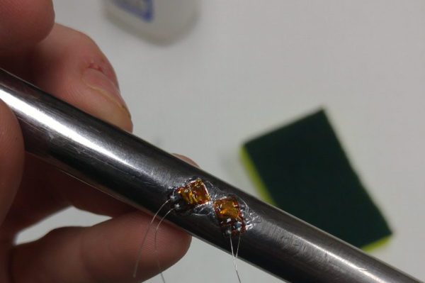
[Taylor Schweizer]’s four-part series on torque is pretty comprehensive. The link above is to the actual build of his DIY torque transducer, but the preceding three installments are well worth the read too. [Taylor] describes himself as an e-waste connoisseur and tantalizes us with the possibility that his build will be with salvaged parts, but in the end a $20 bag of strain gauges and an LM358 were the quickest way to his proof of concept. The strain gauges were super-glued to a socket extension, hot glue was liberally applied for insulation and strain relief, and the whole thing wired up to a Teensy for data capture. A quick script and dump of the data to Excel and you’ve got a way to visualize torque.

An LCD display for real-time measurements is in the works, as are improvements to the instrumentation amp – for which [Taylor] might want to refer to [Bil Herd]’s or [Brandon Dunson]’s recent posts on the subject.

[via r/arduino]

Building A Digital Scale From Scratch

duplo

[Raivis] was given a particular task at his university – find a way to measure how many Duplo bricks are stacked together. There are a number of ways to do this, everything from computer vision to using a ruler, but [Raivis] chose a much more educational method. He built a digital scale from scratch out of a strain gauge and a Wheatstone bridge. The build log is immensely educational and provides some insight into the challenges of weighing things digitally.

A strain gauge is a simple piece of equipment, just a small force sensitive resistor. When attached to a metal bar and a force is applied, the resistance inside the strain gauge changes, but not by much. There’s only a few micro Ohms difference between the minimum and maximum of [Raivis]’ load cell, so he needed a way to measure very slight changes in resistance.

The solution was a Wheatstone bridge, or four resistors arranged in a square. When one of the resistors in the bridge is replaced with a strain gauge, very small changes in resistance  can be measured.

With a custom ‘duino amplifier shield, [Raivis] can measure the resistance of his load cell with 10-bit resolution, or a maximum weight of 1.32 kg with a resolution of two and a half grams. A single duplo block weighs about 12 grams, so we’ll call this one a success.

Paper Accelerometers For Pennies In The Works

Cheap paper accelerometers? Put us down for a dozen to start. They’re not quite ready for mass production yet but it looks like they’re on the way.

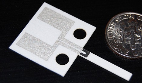
[George Whitesides] led a team to develop the new technology that uses simple manufacturing methods to produce the sensor seen above. Graphite and silver inks were screen printed onto heavy paper. The single limb sticking out from the body of the sensor is a separate piece of paper that bends the carbon area when force is applied. This changes the carbon’s resistance which is measured using a Wheatstone bridge constructed by gluing resistors to the device.

It sounds unsophisticated compared to most of the accelerometer modules we’re used to, but if you need a sensor that detects sudden motion this sounds like the perfect part. Now who wants to be the first person to replicate this in their basement?

[Thanks Fabien]