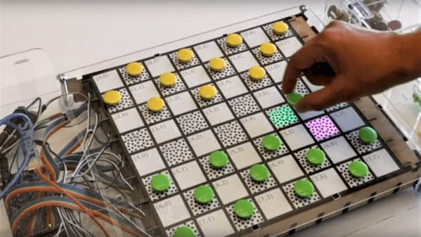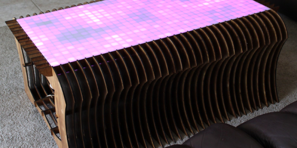
When makers take to designing furniture for their own home, the results are spectacular. For their senior design project, [Phillip Murphy] and his teammates set about building a smart table from the ground up. Oh, and you can also use it to play games, demonstrated in the video below.
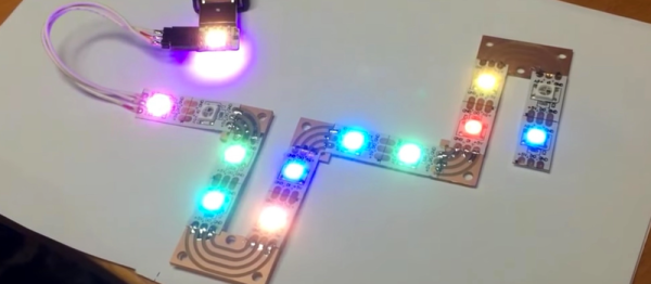
The table uses 512 WS2812 pixels in a 32 x 16 array which has enough resolution to play a selection of integrated games — Go, 2-player Tetris, and Tron light cycle combat — as well as some other features like a dancing bird party mode — because what’s the point of having a smart table if it can’t also double as rave lighting?
A C2000-family microcontroller on a custom board is the brains, and is controlled by an Android app via Bluetooth RN-42 modules. The table frame was designed in Sketchup, laser-cut, and painstakingly stained. [Murphy] and company used aluminum ducting tape in each of the ‘pixels’, and the table’s frame actually forms the pixel grid. Check out the overview and some of the games in action after the break.