PCIe For Hackers: External PCIe And OCuLink

We’ve seen a lot of PCIe hacks on Hackaday, and a fair few of them boil down to hackers pulling PCIe somewhere it wasn’t meant to be. Today, we routinely can find PCIe x1, x2 and x4 links sitting around in our tech, thanks to the proliferation of things like NVMe SSDs, and powerful cheap SoCs that make PCIe appear at your fingertips.

In the PCIe For Hackers series, we’ve talked about PCIe and how cool it is, all the benefits it has for hackers, gave you layout and interconnection rules, and even went into things like PCIe switches and bifurcation. However, there’s one topic we didn’t touch much upon, and that’s external PCIe links.

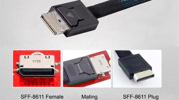
Today, I’d like to tell you about OCuLink – a standard that hackers might not yet know as an option whenever we need to pull PCIe outside of your project box, currently becoming all that more popular in eGPU space. Essentially, OCuLink is to PCIe is what eSATA is to SATA, and if you want to do an eGPU or an external “PCIe socket”, OCuLink could work wonders for you.

Respectable Capabilities

Just like any high-speed standard, PCIe has some tight requirements when things get fast. Even though PCIe is known to be not as sensitive to lower-quality links due to its link training and generation downgrade abilities, at higher link speeds, even through-hole vs SMD sockets can make a difference. So, if you want to go high-throughput, you want proper cabling and connectors, intended for out-of-chassis use – and OCuLink gives you all of this, at a low price.

Continue reading “PCIe For Hackers: External PCIe And OCuLink”

Getting PCIe Working On The New Pi 5

After the Pi 4 released, a discovery was quickly made that the internals of the popular single-board computer use PCIe to communicate with each other. This wasn’t an accessible PCIe bus normally available in things like desktop computers for expansion cards, though; this seemed to be done entirely internally. But a few attempts were made to break out the PCIe capabilities and connect peripherals to it anyway, with varying levels of success. The new Pi 5 seems to have taken that idea to its logical conclusion and included a PCIe connector, and [George] is showing us a way to interface with this bus.

The bus requires the port to be enabled, but once that’s done it’s ready to be used. First, though, some support circuitry needs to be worked out which is why [George] is reverse engineering the system to see what’s going on under the hood. There are a few handshakes that happen before it will work with any peripherals, but with that out of the way a PCIe card can be connected. [George] removed the connector to solder wires to the board directly in order to connect a proper PCIe port allowing a variety of cards to be connected, in this case a wireless networking card and an old Firewire card. This specific build only allows Gen 1 speeds, but the bus itself supports faster connections in theory with better wiring and support circuitry.

While it might not be the prettiest solution, as [George] admits, it does a great job of showing the inner workings of this communication protocol and its use in the new, more powerful Raspberry Pi 5. This makes a lot of things more accessible, such as high-speed PCIe HATs allowing for a wide range of expansion for these popular single-board computers, which wouldn’t have been possible before. If you’re still stuck with a Pi 4, though, don’t despair. You can still access the PCIe bus on these older models but it’ll take a little bit more work.

Thanks to [CJay] for the tip!

Continue reading “Getting PCIe Working On The New Pi 5”

The IMac GPU Becomes Upgradeable, With PCIe

Over its long lifetime, the Apple iMac all-in-one computer has morphed from the early CRT models through those odd table-lamp machines into today’s beautiful sleek affairs. They look pretty, but is there anything that can be done to upgrade them? Maybe not today’s ones, but the models from the mid-2000s can be given some surprising new life. [LowEndMac] have featured a 2006 24″ model that’s received a much more powerful GPU, something we’d have thought to be impossible.

The iMacs from that era resemble a monitor with a slightly chunkier back, in which resides the guts of the computer. By then the company was producing machines with an x86 processor, and their internals share a lot of similarities with a laptop of the period. The card is a Mac Radeon model newer than the machine would ever be used with, and it sits in a chain of mini PCIe to PCIe adapters. Even then it can’t drive the original screen, so a replacement panel and power supply are taken from another monitor and grafted into the iMac case. This along with a RAM and SSD upgrade makes this about the most upgraded a 2006 iMac could be.

Of course, another approach is to simply replace the whole lot with an Intel NUC.

PCIe For Hackers: Our M.2 Card Is Done

We’ve started designing a PCIe card last week, an adapter from M.2 E-key to E-key, that adds an extra link to the E-key slot it carries – useful for fully utilizing a few rare but fancy E-key cards. By now, the schematic is done, the component placement has been figured out, and we only need to route the differential pairs – should be simple, right? Buckle up.

Getting Diffpairs Done

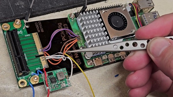
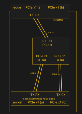
PCIe needs TX pairs connected to RX on another end, like UART – and this is non-negotiable. Connectors will use host-side naming, and vice-versa. As the diagram demonstrates, we connect the socket’s TX to chip’s RX and vice-versa; if we ever get confused, the laptop schematic is there to help us make things clear. To sum up, we only need to flip the names on the link coming to the PCIe switch, since the PCIe switch acts as a device on the card; the two links from the switch go to the E-key socket, and for that socket’s purposes, the PCIe switch acts as a host.

While initially routing this board, I absolutely forgot about one more important thing for PCIe – series capacitors on every data pair, on the host TX side of the link. We need three capacitor pairs here – on TX of the PCIe switch uplink, and two pairs on TX side of the switch – again, naming is host-side. I only remembered this after having finished routing all the diffpairs, and, after a bit of deliberation, I decided that this is my chance to try 0201 capacitors. For that, I took the footprints from [Christoph]‘s wonderful project, called “Effect of moon phase on tombstoning” – with such a name, these footprints have got to be good.

We’ve talked about differential pair calculations before in one of the PCIe articles, and there was a demo video too! That said, let’s repeat the calculations on this one – I’ll show how to get from “PCB fab website information” to “proper width and clearance diffpairs”, with a few fun shortcuts. Our setup is, once again, having signals on outer layers, referenced to the ground layer right below them. I, sadly, don’t yet understand how to calculate differential impedance for signal layers sandwiched between two ground planes, which is to say – if there’s any commenters willing to share this knowledge, I’d appreciate your input tremendously! For now, I don’t see that there’d be a tangible benefit to such an arrangement, anyway.

Continue reading “PCIe For Hackers: Our M.2 Card Is Done”

PCIe For Hackers: An M.2 Card Journey

I’ve designed a few M.2 adapters for my own and my friends’ use, and having found those designs online, people have asked me for custom-made adapters. One of these requests is quite specific – an adapter that adds one more PCIe link to an E-key M.2 slot, the kind of slot you will see used in laptops for WiFi cards.

See, the M.2 specification allows two separate PCIe links connected to the E-key slot; however, no WiFi cards use this apart from some really old WiGig-capable ones, and manufacturers have long given up on connecting a second link. Nevertheless, there are some cards like the Google Coral M.2 E-key dual AI accelerator and the recently announced uSDR, that do indeed require the second link – otherwise, only half of their capacity is available.

It’s not clear why both Google and WaveletSDR designed for a dual-link E-key socket, since those are a rare occurrence; for the Google card, there are plenty of people complaining that the board they bought just doesn’t fully work. In theory, all you need to do to help such a situation, is getting a second PCIe link from somewhere, then wiring it up to the socket – and a perfect way to do it is to get a PCIe switch chip. You will lose out on some bandwidth because the uplink PCIe connection of the switch can only go so fast; for things like this AI accelerator, it’s not much of a problem since the main point is to get the second device accessible. For the aforementioned SDR, it might turn out useless, or you might win some but lose some – can’t know until you try! Continue reading “PCIe For Hackers: An M.2 Card Journey”

PCIe For Hackers: Extracting The Most

So, you now know the basics of approaching PCIe, and perhaps you have a PCIe-related goal in mind. Maybe you want to equip a single-board computer of yours with a bunch of cheap yet powerful PCIe WiFi cards for wardriving, perhaps add a second NVMe SSD to your laptop instead of that Ethernet controller you never use, or maybe, add a full-size GPU to your Raspberry Pi 4 through a nifty adapter. Whatever you want to do – let’s make sure there isn’t an area of PCIe that you aren’t familiar of.

Splitting A PCIe Port

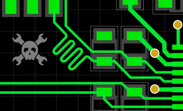
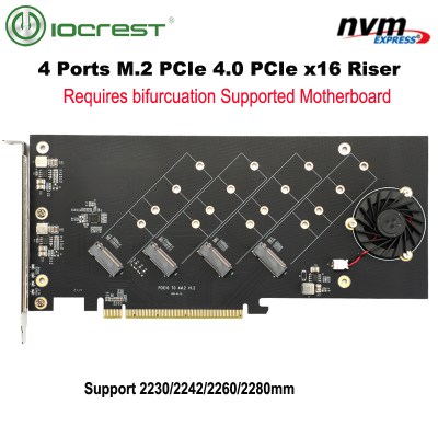
You might have heard the term “bifurcation” if you’ve been around PCIe, especially in mining or PC tinkering communities. This is splitting a PCIe slot into multiple PCIe links, and as you can imagine, it’s quite tasty of a feature for hackers; you don’t need any extra hardware, really, all you need is to add a buffer for REFCLK. See, it’s still needed by every single extra port you get – but you can’t physically just pull the same clock diffpair to all the slots at once, since that will result in stubs and, consequently, signal reflections; a REFCLK buffer chip takes the clock from the host and produces a number of identical copies of the REFCLK signal that you then pull standalone. You might have seen x16 to four NVMe slot cards online – invariably, somewhere in the corner of the card, you can spot the REFCLK buffer chip. In a perfect scenario, this is all you need to get more PCIe out of your PCIe.

Continue reading “PCIe For Hackers: Extracting The Most”

PCIe For Hackers: Link Anatomy

Last time, we looked over diffpairs, their basics, routing rules and the notorious tolerances of PCIe when it comes to diffpairs. Now, let’s take a look at the exact signals that make PCIe tick, as well as give you an overview of which sockets you can get PCIe on.

I separate PCIe sockets into two categories – desktop sockets, which are the usual 1x, 16x, or perhaps x4 PCIe sockets we see on desktop motherboards — and mobile sockets: mPCIe and M.2. There are also sockets like ExpressCard that are still found on some older laptops, but they have definitely fallen out of relevance. On mobile, M.2 is the way forward when it comes to PCIe – if you’re interested, I’ve written a short series talking about everything M.2 before.

On these sockets, most signals will be optional and some signals will be socket-specific, but there are some signals required in any PCIe device. Of course, the first group of required signals is the PCIe diffpairs themselves.

Continue reading “PCIe For Hackers: Link Anatomy”