Reflow Solder Your Micro SD To Ensure It Doesnt Go Anywhere

SD cards are great inexpensive storage for your embedded project. Using SPI,  they only take a few wires to hook up, and every micro-controller has a FAT file system interface to drop in your project. Problem with SD cards are the connectors.

Usually connectors cost more than the brains of your project,  and the friction fit, spring loaded contacts are not ideal for temperature swings, humidity and high vibration applications. Wouldn’t it be nice if you could just solder the thing down, especially if you know you are never going to remove it?

[Timothée] decided to try and succeeded in reflow soldering a Micro SD card direct to a breakout board. While starting as a what if experiment, the PCB was laid out in Ki-Cad and sent off to a fab. Once returned the Micro SD was fluxed, tinned and fluxed again, then reflowed using an IR setup.

The end result is a handy breakout board where you never have to worry about someone swiping the card to jam in their camera, and is ready for any breadboard project.

Old Ham Wisdom Leads To Better Aluminum Painting

When [bdk6] tried painting aluminum for electronic projects, he found it didn’t tend to stay painted. It would easily scratch off or, eventually, even flake off. The problem is the paint doesn’t want to adhere to the aluminum oxide coating around the metal. Research ensued, and he found an article in an old ham radio magazine about a technique that he could adapt to get good results painting aluminum.

Actually, paint apparently adheres poorly, even to non-oxidized aluminum. So the plan is to clean and remove as much aluminum oxide as possible. Then the process will convert the aluminum surface to something the paint sticks to better. Of course, you also need the right kind of paint.

The key ingredients are phosphoric acid and zinc phosphate. Phosphoric acid is found in soft drinks, but is also sold as a concrete and metal prep for painting. The zinc phosphate is part of a special paint known as a self-etching primer.

Cleaning takes soap, elbow grease, and sandpaper. The next step is a long soak in the phosphoric acid. Then you apply a few coats of self-etching primer and sand. Once it is all set, you can paint with your normal paint. That’s usually epoxy-based paint for [bdk6].

Of course, you can also dye aluminum while anodizing it. Soldering aluminum also has its challenges.

The SSD described, a green board with a ZIP connector, a controller chip and two out of four NAND chips populated. There's traces of flux on the chip, as it hasn't been washed after soldering yet.

ZIF HDDs Dying Out? Here’s An Open-Source 1.8″ SSD

A lot of old technology runs on parts no longer produced – HDDs happen to be one such part, with IDE drives specifically being long out of vogue, and going extinct to natural causes. There’s substitutes, but quite a few of them are either wonky or require expensive storage medium. Now, [dosdude1] has turned his attention to 1.8 ZIF IDE SSDs – FFC-connected hard drives that are particularly rare and therefore expensive to replace, found in laptops like the Macbook Air 1,1 2008 model. Unsatisfied with substitutes, he’s designed an entire SSD from the ground up around an IDE SSD controller and NAND chips. Then, he made the design open-source and filmed an assembly video so that we can build our own. Take a look, we’ve put it below the break!

For an open-source design, there’s a respectable amount of work shared with us. He’s reverse-engineered some IDE SSDs based on the SM2236 controller to design the schematic, and put the full KiCad files on GitHub. In the video, he shows us how to assemble this SSD using only a hot air station and a soldering iron, talks about NAND matching and programming software intricacies, and shows the SSD working in the aforementioned Macbook Air. Certainly, assembly would have been faster and easier with a stencil, but the tools used work great for what’s a self-assembly tutorial!

Continue reading “ZIF HDDs Dying Out? Here’s An Open-Source 1.8″ SSD”

On the left, the Thunderbolt chip as mounted on the motherboard originally. On the right, the shim installed in place of a Thunderbolt BGA chip, with the IPEX connector soldered on

Macbook Gets NVMe SSD With Help Of A BGA-Imitating PCB

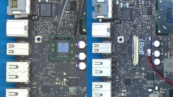
Recently, we stumbled upon a video by [iBoff], adding an M.2 NVMe port to a 2011-2013 MacBook. Apple laptops never came with proper M.2 ports, especially the A1278 – so what’s up? The trick is – desoldering a PCIe-connected Thunderbolt controller, then soldering a BGA-like interposer PCB in place of where the chip was, and pulling a cable assembly from there to the drive bay, where a custom adapter PCB awaits. That adapter even lets you expose the PCIe link as a full-sized PCIe 4x slot, in case you want to connect an external GPU instead of the NVMe SSD!

The process is well-documented in the video, serving as an instruction manual for anyone attempting to install this specific mod, but also a collection of insights and ideas for anyone interested in imitating it. The interposer board ships with solder balls reballed onto it, so that it can be installed in the same way that a BGA chip would be – but the cable assembly connector isn’t installed onto the interposer, since it has to be soldered onto the mainboard with hot air, which would then melt the connector. The PCB that replaces the optical drive makes no compromises, either, tapping into the SATA connector pins and letting you add an extra 2.5mm SATA SSD.

Adding an NVMe drive is an underappreciated way to speed up your old laptop, and since they’re all PCIe under the hood, you can really get creative with the specific way you add it. You aren’t even limited to substituting obscure parts like Thunderbolt controllers – given a laptop with a discrete GPU and a CPU-integrated one, you could get rid of the discrete GPU and replace it with an adapter for one, or maybe even two NVMe drives, and all you need is a PCB that has the same footprint as your GPU. Sadly, the PCB files for this adapter don’t seem to be open-source, but developing a replacement for your own needs would be best started from scratch, either way.

We’ve seen such an adapter made for a Raspberry Pi 4 before, solderable in place of a QFN USB 3.0 controller chip and exposing the PCIe signals onto the USB 3 connector pins. However, this one takes it up a notch! Typically, without such an adapter, we have to carefully solder a properly shielded cable if we want to get a PCIe link from a board that never intended to expose one. What’s up with PCIe and why is it cool? We’ve talked about that in depth!

Continue reading “Macbook Gets NVMe SSD With Help Of A BGA-Imitating PCB”

Screenshot of a logic analyzer software, showing the SDA channel being split into three separate traces

I2C Tap Helps Assign Blame For SDA Conflicts

If you’ve ever debugged a misbehaving I2C circuit, you probably know how frustrating it can be. Thankfully [Jim] over at Hackaday.io, has a proto-boardable circuit that can help!

Inter-integrated circuit bus (aka I2C) uses open collector outputs on a two wire interface. Open collector means a device connected to the I2C bus can only pull the bus down to ground. Chips never drive a logic “HIGH” on the wires. When nothing is driving the lines low, a weak resistor pulls the lines up to VCC. This is a good thing, because I2C is also a multidrop bus — meaning many devices can be connected to the bus at the time. Without open collector outputs, one chip could drive a high, while another drives a low – which would create a short circuit, possibly damaging both devices.

Even with all this protection, there can be problems. The SCL and SDA lines in the I2C communication protocol are bidirectional, which means either a controller or a peripheral can pull it low. Sometimes, when tracing I2C communications you’ll need to figure out which part is holding the line low. With many devices sharing the same bus, that can become nigh-impossible. Some folks have tricks with resistors and analog sampling, but the tried and true method of de-soldering and physically lifting chip pins off the bus often comes into play.

[Jim’s] circuit splits SDA signal into controller-side and peripheral-side, helping you make it clear who is to blame for hiccups and stray noise. To do that, he’s using 6N137 optoisolators and LMV393 comparators. [Jim] shared a NapkinCAD schematic with us, meant to be replicate-able in times of dire need. With this design, you can split your I2C bus into four separate channels – controller-side SDA, peripheral-side SDA, combined SDA and SCL. 4 Channels might be a lot for a scope, but this is no problem for today’s cheap logic analyzers.

Continue reading “I2C Tap Helps Assign Blame For SDA Conflicts”

Hackaday Podcast 164: Vintage NASA Soldering, Mouse Bites, ATTiny85 Graphics, And PVC Pontoons

Join Hackaday Editor-in-Chief Elliot Williams and Managing Editor Tom Nardi as they review the most interesting hacks and stories of the previous week. This time we’ll start things off by talking about the return of in-person events, and go over several major conventions and festivals that you should add to your calendar now. Then we’ll look at a NASA training film from the Space Race, an interesting radio-controlled quirk that Tesla has built into their cars for some reason, a very promising autonomous boat platform, and some high performance visuals generated by an ATtiny85. Stick around to find out what happens with an interplanetary probe looses its ride to space, and why the best new enclosure for your Raspberry Pi 4 might be a surveillance camera.

Check out the links below if you want to follow along, and as always, tell us what you think about this episode in the comments below!

Direct Download

Continue reading “Hackaday Podcast 164: Vintage NASA Soldering, Mouse Bites, ATTiny85 Graphics, And PVC Pontoons”

A Nitrogen Soldering Iron Review

If you’ve ever welded, you know that some welders blow a shield gas over the work for different reasons. For example, you often use a gas to displace oxygen from the area and avoid oxidation. You can also solder using a nitrogen shield. This allows higher temperatures and a reduction of flux required in the solder. Wave soldering often uses nitrogen, and JBC offers a soldering iron that can employ nitrogen shield gas. [SDG Electronics] puts that iron through its paces in the video below.

As you might expect, this isn’t a $50 soldering iron. The price for the iron is just under $1,000 and that doesn’t include the power supply or the nitrogen source. The nitrogen generator that converts compressed air into nitrogen is particularly expensive so [SDG] just used a cylinder of gas.

Continue reading “A Nitrogen Soldering Iron Review”