Op-Amp Challenge: MOSFETs Make This Discrete Op Amp Tick

When it comes to our analog designs, op-amps tend to be just another jellybean part. We tend to spec whatever does the job, and don’t give much of a thought as to the internals. And while it doesn’t make much sense to roll your own op-amp out of discrete components, that doesn’t mean there isn’t plenty to be learned from doing just that.

While we’re more accustomed to seeing [Mitsuru Yamada]’s digital projects, he’s no stranger to the analog world. In fact, this project is a follow-on to his previous bipolar transistor op-amp, which we featured back in 2021. This design features MOSFETs rather than BJTs, but retains the same basic five-transistor topology as the previous work, with a differential pair input stage, a gain stage, and a buffer stage. Even the construction of the module is similar, using his trademark perfboard and ultra-tidy wiring.

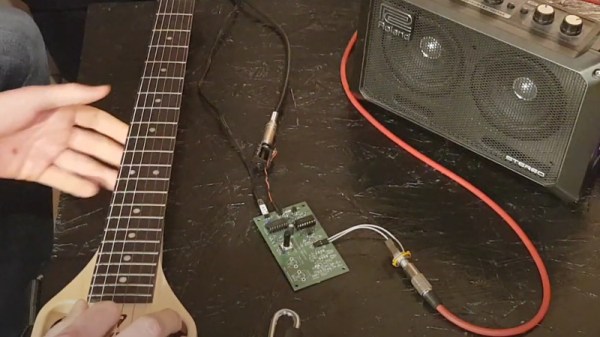
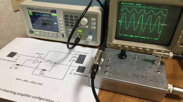
Also new is a flexible evaluation unit for these discrete op-amp modules. This very sturdy-looking circuit provides an easy way to configure the op-amp for testing in inverting, non-inverting, and transimpedance mode, selecting from a range of feedback resistors, and even provides a photodiode input. The video below shows the eval unit in action with the CMOS module, as well as highlights the excellent construction [Mitsuru Yamada] is known for.

Looking for some digital goodness? Check out the PERSEUS-8, a 6502 machine we wish had been a real product back in the day.

Continue reading “Op-Amp Challenge: MOSFETs Make This Discrete Op Amp Tick”

A CMOS Ring Modulator Pedal

Earlier this year, we featured an unusual radio receiver that took the very traditional superhetrodyne design and implemented it in an unexpected fashion without any inductors, using instead a combination of 74HC logic chips and op-amps. Its designer [acidbourbon] remarks that the circuit bears a striking resemblance to a ring modulator,so has taken it down that path by producing a 74HC based ring modulator guitar pedal.

In both circuits, a 74HC4046 phase-locked loop chip serves as an oscillator, driving a 74HC4051 analogue switch chip that performs the mixer task. The extra-op-amp filter and demodulator circuitry from the radio is omitted, and the oscillator frequency moved down to the audio range. The result can be heard in the video, and we probably agree with him that it’s not quite the same as a classic ring modulator. This lies in the type of mixer, the diodes used in a traditional circuit have a forward voltage to overcome before they start or end conducting, while the CMOS switch chip does so immediately on command.

The 4000 series CMOS and their descendants are a fascinating family with many unexpected properties that our colleague Elliot Williams has gone into detail with for his Logic Noise series. Meanwhile take a look at our coverage of the original radio.

Continue reading “A CMOS Ring Modulator Pedal”

the 3 needle ammeters that make up the face of the clock

IC Clock Uses Ammeters For A Unique Time-Telling Display

It is a rite of passage for hackers to make a clock out of traditionally not-clock items. Whether it be blinking LEDs or servos to move the hands, we have all crafted our own ways of knowing when it currently is. [SIrawit] takes a new approach to this, by using ammeters to tell the time.

The clock is built using mostly CMOS ICs. A CD4060 generates the 1HZ clock signal, which is then passed to parallel counters to keep track of the hours, minutes, and seconds. [SIrawit] decided to keep the ammeters functioning as intended, rather than replacing the internals and just keeping the needle and face. To convert the digital signal to a varying current, he used a series of MOSFETs connected in parallel to the low side of the ammeters, with different sizes of current-limiting resistors. By sizing these resistors properly, precise movement of the needle could be achieved by turning on or off the MOSFETs. You can see the schematics and learn more about how this is achieved on the project’s GitHub page (at the time of writing, the most recent commits are in the ‘pcb’ branch).

In addition to the custom PCB that holds all the electronics, PCBs help make up the case as well. While the main body of the case is made out of a repurposed junction box, [SIrawit] had a PCB on an aluminum substrate manufactured for the front panel. While the board has no actual traces or electrical significance, this makes for a cheap and easy way to get a precisely cut piece of aluminum for your projects, with a sharp-looking white solder mask to boot.

We love to see cool and unique ways to tell the time, such as using Nixie Tubes to spell out the time in binary!

Continue reading “IC Clock Uses Ammeters For A Unique Time-Telling Display”

Cool Binary Clock Uses Old-School LEDs And A Fancy Graphic PCB

Ah, the 5mm LED. Once a popular choice, they’ve been supplanted in modernity by smaller SMD components and/or more capable RGB parts in recent years. However, they’re still able to do the job and are a great way to give your project that proper homebrew look. [Ian Dunn] chose those very parts to produce his 4017 Decade Binary Clock.

The clock uses only digital logic ICs to tell the time – there are no microcontrollers here! After four or five iterations over almost a whole year, [Ian] was finally able to coax the circuit into reliable operation. As you’d expect, it relies on a 32.768 kHz crystal to provide a stable clock. Fed into a 4060 binary ripple counter, that clock is divided down 14 times to deliver a 2Hz square wave. This then goes through a 4027 flip flop to get the desired 1Hz signal. From there, a bunch of extra logic handles counting the seconds, minutes, and hours, and resetting the counters as appropriate.

The PCB that houses the project is printed on directly by a flatbed inkjet printer, which [Ian] purchased when inspired by our previous article on how to get your PCBs made at the mall. He didn’t actually use it to make the PCB in this case, but the flatbed printer does a great job of putting graphics on the board.

The result is quite an attractive look that might surprise a few electronics enthusiasts who haven’t seen a graphic printed board before. It’s a technique we think could be used to great effect on conference badges, too. If you’ve experimented with similar techniques, be sure to drop us a line!

Silicon Jumpers Make This Wire-Free Breadboard Programmable

There’s no doubting the utility of the trusty solderless breadboard, but you have to admit they’re less than perfect. They’re not ideal for certain types of circuits, of course, but that’s less of a problem than those jumper wires. The careless will end up with their components hopeless tangled in a rat’s nest of jumpers, while the fastidious will spend far more time making the jumpers neat and tidy than actually prototyping the circuit itself. What to do?

One way to crack this nut is to make the solderless breadboard jumperless, too. That’s the idea behind “breadWare” a work-in-progress undertaken by [Kevin Santo Cappuccio]. The idea is to adapt a standard breadboard so that connections between arbitrary pairs of common contact strips — plus the power rails — can be made in software. The trick behind this is a matrix of analog CMOS switch chips, specifically the MT8816AP. Each chip’s 128 crosspoint switches can handle up ± 12 volts, so there are plenty of circuits that can use these programmable silicon jumpers.

[Kevin] is currently on version 0.2, which is sized to fit under a solderless breadboard and make a compact package. He shared details on how he’s connecting to the breadboard contacts, and it looks like a painful process: pull out the contact, cut a small tab at the gutter-end, and bend it down so it forms a lead for a through-hole in the PCB. It seems like a lot of work, and there must be a better way; [Kevin] is clearly open to suggestions.

While we’ve seen crosspoint switching used to augment solderless breadboarding before, we find this project pleasing in its simplicity. The thought of tossing out all those jumpers is certainly tempting.

Inside An Oscillator With [Ken Shirriff]

We are always glad to see [Ken Shirriff] tear into something new and this month he’s looking inside a quartz oscillator module. Offhand, you’d think there’s not much to these. A slab of quartz and some sort of inverter, right? But as [Ken] mentions, “There’s more happening in the module than I expected…”

If you’ve ever wanted to decap devices, big hybrid modules like these are a good way to get started since you don’t need exotic chemicals to get at the insides. [Ken] managed to break the fragile crystal wafer on the way in. Inside was also a small CMOS IC die. Time to get out the microscope.

If you follow [Ken’s] blog, you know he’s no stranger to analyzing IC dice. The oscillator IC is a pretty standard Colpitts oscillator but it also provides a programmable divider and output drive.

The circuit uses some unusually configured capacitors. [Ken] takes the time to point out CMOS logic structures throughout. If you haven’t seen one of [Ken’s] deep dives before, before, it’s a great introduction.

You can learn more about crystal oscillator theory. We used some test equipment to characterize a crystal a few years ago.

Gorgeous Clock, And Not A Line Of Code In Sight

[Harry] dropped us a note to let us know about his completed CMOS clock project, and we’re delighted that he did because it’s gorgeous. It’s a digital clock satisfyingly assembled entirely from hardware logic, without a single line of code. There are three main parts to this kind of digital clock: ensuring a stable time base, allowing for setting the time, and turning the counter outputs into a numerical display.

Keeping accurate time is done with a 32.768 kHz crystal, and using CMOS logic to divide that down to a 1 Hz square wave. From there, keeping track of hours and minutes and seconds is mostly a matter of having counters reset and carry at the appropriate times. Setting the clock is done by diverting the 1 Hz signal so that it directly increments either the hours or minutes counter. The counter values are always shown “live” on six 7-segment displays, which makes it all human-readable.

The whole thing is tastefully enclosed in a glass dome which looks great, but [Harry] helpfully warns prospective makers that such things have an unfortunate side effect of being a fingerprint magnet. Schematics and design files are provided for those who want a closer look.

This clock uses a crystal and divider, but there’s another method for keeping accurate time and that’s to base it off the alternating current frequency of power from the grid. Not a bad method, albeit one that depends on being plugged into the wall.