When you can get a WiFi-enabled microcontroller for $3, it’s little surprise that many of the projects we see these days have ditched Ethernet. But the days of wired networking are far from over, and there’s still plenty of hardware out there that can benefit from being plugged in. But putting an Ethernet network into your project requires a switch, and that means yet another piece of hardware that needs to get crammed into the build.
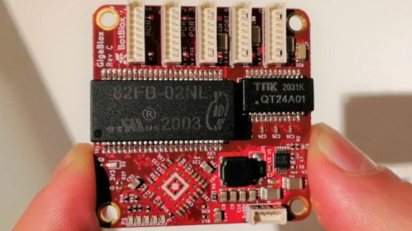
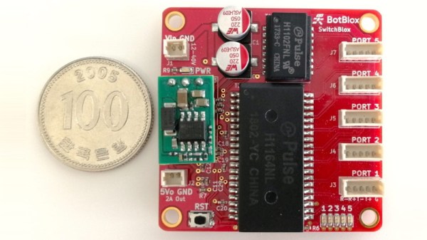
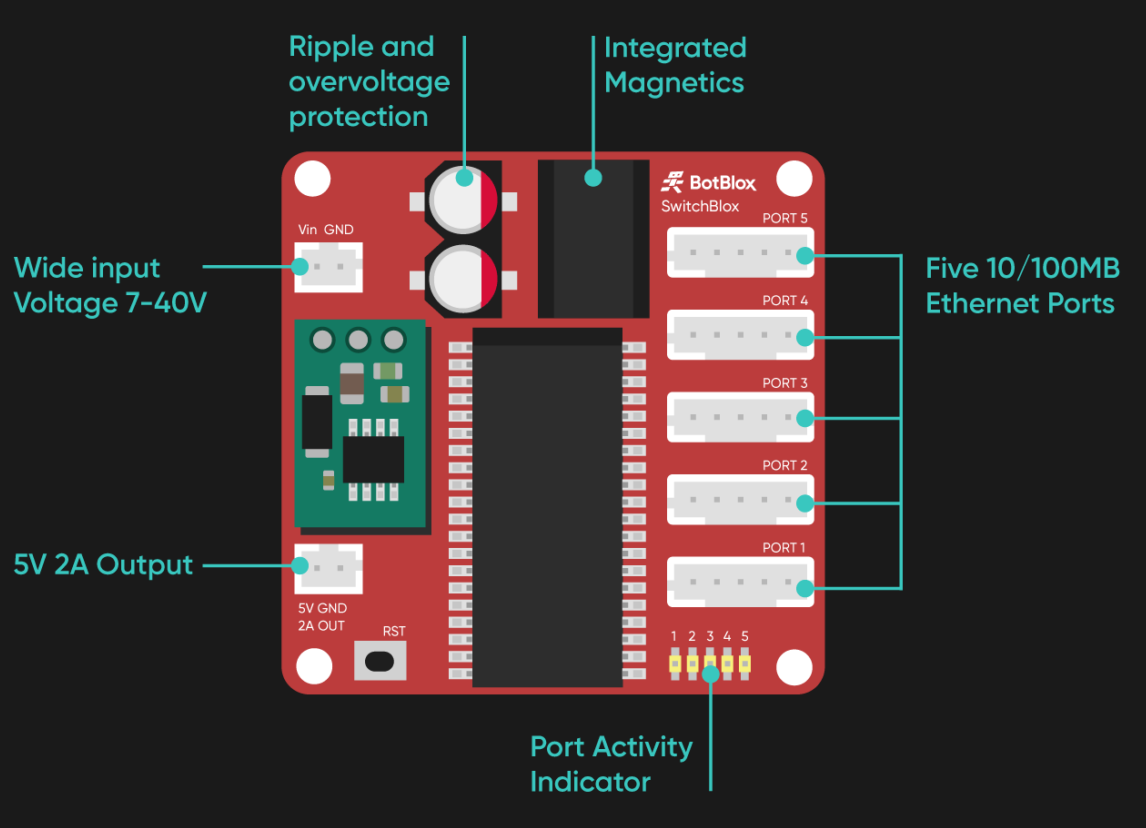
 Seeing the need for a small and lightweight Ethernet switch, BotBlox has developed the SwitchBlox. This 45 mm square board has everything you need to build a five device wired network, and nothing you don’t. Gone are the bulky RJ45 jacks and rows of blinkenlights, they won’t do you any good on the inside of a robot’s chassis. But that’s not to say it’s a bare bones experience, either. The diminutive switch features automatic crossover, support for input voltages from 7 V all the way up to 40 V, and management functions accessible over SPI.
If you want to get up and running as quickly as possible, a fully assembled SwitchBlox is available to purchase directly from BotBlox for £149.00. But if you’re not in any particular rush and interested in saving on cost, you can spin up your own version of the Creative Commons licensed board. The C++ management firmware and Python management GUI isn’t ready for prime time just yet, but you’ll be able to build a “dumb” version of the switch with the provided KiCad design files.
The published schematic in their repo uses a Microchip KSZ8895MQXCA as the Ethernet controller, with a Pulse HX1344NL supplying the magnetics for all the ports in a single surface mount package. Interestingly, the two images that BotBlox shows on their product page include different part numbers like H1102FNL and PT61017PEL for the magnetics, and the Pulse H1164NL for the Ethernet controller.
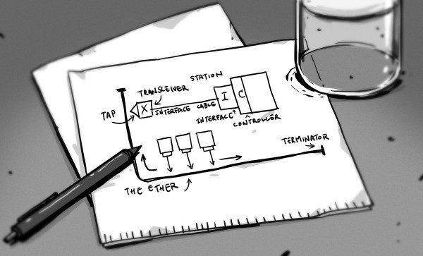
Make Networks Wired Again
There’s no question that WiFi has dramatically changed the way we connect devices. In fact, there’s an excellent chance you’re currently reading these words from a device that doesn’t even have the capability to connect to a wired network. If you’re looking to connect a device to the Internet quickly, it’s tough to beat.
But WiFi certainly isn’t perfect. For one, you have to contend with issues that are inherent to wireless communications such as high latency and susceptibility to interference. There’s also the logistical issues involved in making that initial connection since you need to specify an Access Point and (hopefully) an encryption key. In comparison, Ethernet will give you consistent performance in more or less any environment, and configuration is usually as simple as plugging in the cable and letting DHCP sort the rest out.
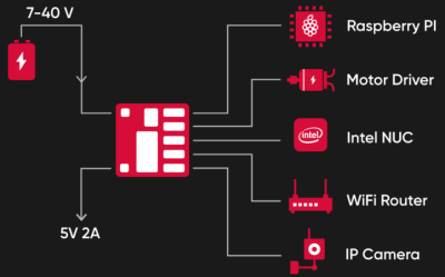 Unfortunately, that whole “plugging in” part can get tricky. Given their size, putting an Ethernet switch into your project to act as an internal bus only works if you’ve got space to burn and weight is of little concern. So as appealing as it might be to build a network into your robot to connect the Raspberry Pi, motor controllers, cameras, etc, it’s rarely been practical.
This little switch could change that, and the fact it’s released under an open source license means hackers and makers will be free to integrate it into their designs. With the addition of an open source management firmware, this device has some truly fascinating potential. When combined with a single board computer or suitably powerful microcontroller, you have the makings of a fully open source home router; something that the privacy and security minded among us have been dreaming of for years.