DIY Loading Coil Shortens Antenna Lengths

A newly licensed amateur radio operator’s first foray into radios is likely to be a VHF or UHF radio with a manageable antenna designed for the high frequencies in these radio bands. But these radios aren’t meant for communicating more than a double-digit number of kilometers or miles. The radios meant for long-distance communication use antennas that are anything but manageable, as dipole antennas for the lowest commonly used frequencies can often be on the order of 50 meters in length. There are some tricks to getting antenna size down like folding the dipole in all manner of ways, but the real cheat code for reducing antenna size is to build a loading coil instead.

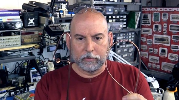
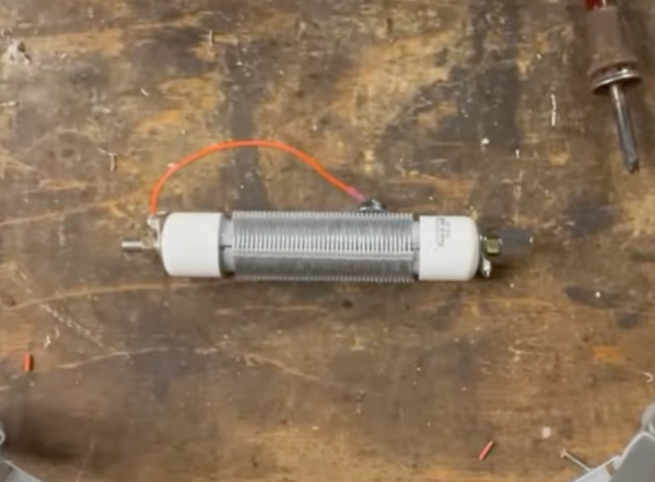
As [VA5MUD] demonstrates, a loading coil is simply an inductor that is placed somewhere along the length of the antenna which makes a shorter antenna behave as a longer antenna. In general, though, the inductor needs to be robust enough to handle the power outputs from the radio. There are plenty of commercial offerings but since an inductor is not much more than a coil of wire, it’s entirely within the realm of possibility to build them on your own. [VA5MUD]’s design uses a piece of PVC with some plastic spacers to wind some thick wire around, and then a customized end cap with screw terminals attached to affix the antenna and feedline to. Of course you’ll need to do a bit of math to figure out exactly how many turns of wire will be best for your specific situation, but beyond that it’s fairly straightforward.

It’s worth noting that the coil doesn’t have to be attached between the feedline and the antenna. It can be placed anywhere along the antenna, with the best performance typically being at the end of the antenna. Of course this is often impractical, so a center-loaded coil is generally used as a compromise. Coils like these are not too hard to wind by hand, but for smaller, lower-current projects it might be good to pick up a machine to help wind the coils instead.

Continue reading “DIY Loading Coil Shortens Antenna Lengths”

Cascade Failures, Computer Problems, And Ohms Law: Understanding The Northeast Blackout Of 2003

We’ve all experienced power outages of some kind, be it a breaker tripping at an inconvenient time to a storm causing a lack of separation between a tree and a power line. The impact is generally localized and rarely is there a loss of life, though it can happen. But in the video below the break, [Grady] of Practical Engineering breaks down the Northeast Blackout of 2003, the largest power failure ever experienced in North America. Power was out for days in some cases, and almost 100 deaths were attributed to the loss of electricity.

[Grady] goes into a good amount of detail regarding the monitoring systems, software simulation, and contingency planning that goes into operating a large scale power grid. The video explains how inductive loads cause reactance and how the effect exacerbated an already complex problem. Don’t know what inductive loads and reactance are? That’s okay, the video explains it quite well, and it gives an excellent basis for understanding AC electronics and even RF electronic theories surrounding inductance, capacitance, and reactance.

So, what caused the actual outage? The complex cascade failure is explained step by step, and the video is certainly worth the watch, even if you’re already familiar with the event.

It would be irresponsible to bring up the 2003 outage without talking about the Texas ERCOT outages just one year ago– an article whose comments section nearly caused a blackout at the Hackaday Data Center!

Continue reading “Cascade Failures, Computer Problems, And Ohms Law: Understanding The Northeast Blackout Of 2003”

Tonewheels Warble In This Organ-Inspired Musical Instrument

Younger readers may not recall the days when every mall had a music store — not the kind where tapes and LPs were sold, but the kind where you could buy instruments. These places inevitably had an employee belting out mall-music to all and sundry on an electric organ. And more often than not, the organist was playing a Hammond organ, with the distinct sound of these instruments generated by something similar to this tonewheel organ robot.

Tonewheels are toothed ferromagnetic wheels that are rotated near a pickup coil. This induces a current that can be amplified; alter the tooth profile or change the speed of rotation, and you’ve got control over the sounds produced. While a Hammond organ uses this technique to produce a wide range of sounds, [The Mixed Signal]’s effort is considerably more modest but nonetheless interesting. A stepper motor and a 1:8 ratio 3D-printed gearbox power a pair of shafts which each carry three different tonewheels. The tonewheels themselves are laser-cut from mild steel and range from what look like spur gears to wheels with but a few large lobes. This is a step up from the previous version of this instrument, which used tonewheels 3D-printed from magnetic filament.

Each tonewheel has its own pickup, wound using a coil winder that [TheMixed Signal] previously built. Each coil has a soft iron core, allowing for the addition of one or more neodymium bias magnets, which dramatically alters the tone. The video below shows the build and a demo; skip ahead to 16:10 or so if you just want to hear the instrument play. It’s — interesting. But it’s clearly a work in progress, and we’re eager to see where it goes. Continue reading “Tonewheels Warble In This Organ-Inspired Musical Instrument”

Otis Boykin’s Precision Passives Propelled The Pacemaker

The simplest ideas can be the ones that change the world. For Otis Boykin, it was a new way to make wirewound precision resistors. Just like that, he altered the course of electronics with his ideas about what a resistor could be. Now his inventions are in everything from household appliances and electronics to missile guidance computers.

While we like to geek out about developments in resistor tech, Otis’ most widely notable contribution to electronics is the control unit he designed for pacemakers, which regulate a person’s heartbeat. Pacemakers are a real-time clock for humans, and he made them more precise than ever.

Street Smarts and Book Smarts

Otis Frank Boykin was born August 29th, 1920 in Dallas, Texas to Sarah and Walter Boykin. Otis’ father was a carpenter who later became a preacher. His mother Sarah was a maid, and she died of heart failure when Otis was only a year old.

Continue reading “Otis Boykin’s Precision Passives Propelled The Pacemaker”

Solving The Mysteries Of Grounding While Improving A Power Supply

Grounding problems and unwanted noise in electrical systems can often lead to insanity. It can seem like there’s no method to the madness when an electrical “gremlin” caused by one of these things pops its head out. When looking more closely, however, these issues have a way of becoming more obvious. In a recent video, [Fesz Electronics] shows us how to investigate some of these problems by looking at a small desktop power supply, modelling it in LTSpice, and reducing the noise on the power supply’s output.

While everything in this setup is properly grounded, including the power supply and oscilloscope, the way the grounding systems interact can contribute to the high amount of noise. This was discovered by isolating the power supply from earth ground using electrical tape (not recommended as a long-term solution) and seeing that the noise was reduced. However, the ripple increased substantially, so a more permanent fix was needed. For that, the power supply was modelled in LTSpice. This is where a key discovery was made: since all the parts of the power supply aren’t ideal, noise can be introduced from the actual real-life electrical behavior of some of the parts. In this case, it was non-ideal capacitance in the transformer.

According to the model, this power supply could be improved by adding a larger capacitor across the output leads, and also by increasing their inductance. A large capacitor was soldered in the power supply and an iron ferrule was added, which decreased the noise level from 100 mV to around 20. Still not perfect, but a much needed improvement to the simple power supply. If, on the other hand, you want to make sure you eliminate that transformer’s capacitance completely, you can always go with a transformerless power supply. That carries other risks, though.

Continue reading “Solving The Mysteries Of Grounding While Improving A Power Supply”

Inductance In PCB Layout: The Good, The Bad, And The Fugly

When current flows through a conductor it becomes an inductor, when there is an inductor there is an electromagnetic field (EM). This can cause a variety of issues during PCB layout if you don’t plan properly, and sometimes we get burned even when we think we have planned for unwanted inductance and the effects that come with them.

When doing high speed logic we need to be able to deliver sudden changes in current to the devices if we want to have proper switching times and logic levels. Unfortunately inductance is usually not a friend in these circumstances as it resists those sudden changes in current. If the high speed devices are driving capacitive loads, which themselves are resisting changes in voltage, even more instantaneous current is needed.

Simply put, inductors resist a change of current, and can act as a low pass filter when in series with the signal or power supply flow. Inductors do this by storing energy in the flux surrounding the conductor. Alternatively capacitors resist a change in voltage (again by storing energy) and can act as a high pass filter when in series with the signal. This makes them a valuable tool in the fight against unwanted inductance in power supply distribution.

In the video below, and the remainder of this article, I’m going to dive into the concept of inductance and how it affects our design choices when laying out circuit boards.

Continue reading “Inductance In PCB Layout: The Good, The Bad, And The Fugly”

Adding Analog Touch To (Nearly) Any Mechanical Keyboard

The new hotness for DIY electronics is mechanical keyboards, and over the past few years we’ve seen some amazing innovations. This one is something different. It adds an analog sensor to nearly any mechanical key switch, does it with a minimal number of parts, and doesn’t require any modification of the switch itself. It’s a reddit thread and imgur post, but the idea is just so good we can overlook the documentation on this one.

The key development behind this type of sensor is realizing that nearly every mechanical keyswitch (Cherry MX, Kalth, Gateron) has a spring in the bottom. A spring is just a coil of wire, and an inductor is just a coil of wire, too. By putting a spiral trace on the PCB of a mechanical keyboard underneath the keyswitch, you can sense the inductance of this spring. This does require a little bit of additional hardware, in this case an LDC1614 inductance to digital converter, but this is an I2C-readable part that can, theoretically, be integrated rather easily with any mechanical keyboard PCB and firmware.

The downside to using the LDC1614 is that sampling is somewhat time-limited, with four channels or individual keys being polled at 500 Hz. This isn’t a problem if the use-case is adding analog to your WASD keys, but it may become a problem for an entire keyboard. Additionally, the LDC1614 is a slightly expensive part, at about $2 USD in quantity 1000. A fully analog keyboard using this technique is going to be pricey.

Right now, the proof-of-concept for this analog mechanical keyswitch is just a 0.1 mm flexible PCB that is shoehorned inbetween a Cherry MX red and a (normal) mechanical keyboard PCB. The next step in the development will be a 2×4 keypad with analog sensors, and opening up the hardware and firmware examples up under a GPL license.