Incredible Soldering In The Name Of Hardware Support

If you’re developing a performant IP-KVM based on the Raspberry Pi, an HDMI capture device that plugs into the board’s CSI port would certainly be pretty high on your list of dream peripherals. Turns out such devices actually exist, and somewhat surprisingly, are being sold for reasonable prices. Unfortunately the documentation for the chipset they use is a bit lacking, which is a problem if you’re trying to wring as much performance out of them as possible.

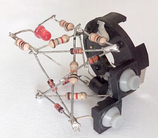
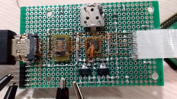
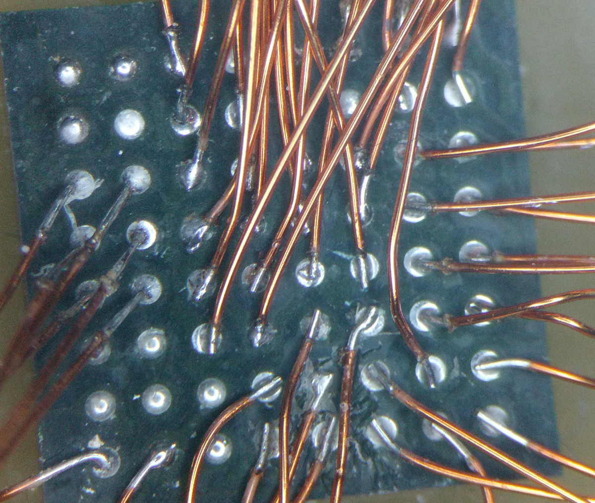
As the creator of Pi-KVM, [Maxim Devaev] needed to truly understand how the Toshiba TC358743 chip used in these capture devices worked, so he decided to build his own version from scratch. In the name of expediency, he didn’t have a proper breakout board made and instead decided to hand-solder the tiny BGA chip directly to some parts bin finds. The resulting perfboard capture device is equal parts art and madness, but more importantly, actually works as expected even with 1080p video signals.

Ultimately, the lessons learned during this experiment will lead to a dedicated KVM board that will plug into the Pi’s expansion header and provide all the necessary hardware in one shot. As [Maxim] explains in the Pi-KVM docs, the move to the CSI connected Toshiba TC358743 cuts latency in half compared to using a USB capture device. That said, USB capture devices will remain fully supported for anyone who just needs a quick way to get things working.

This DIY capture card is a perfect example of how the skills demonstrated while working on a project can be just as impressive as the end result. [Maxim] didn’t set out to hand-solder a BGA HDMI capture chip, it was merely one step in the process towards creating something better. Those intermediary achievements are often lost in the rush to document the final project, so we’re always glad when folks take the time to share them.

[Thanks to Eric for the tip.]

Non-standard circuit boards

Non-standard Circuits: Jazz For Electrons

How creative are you when you make your circuit boards? Do you hunt around for different materials to use for the board? As long as it’s an insulator and can handle the heat of a soldering iron, then anything’s fair game. Or do you use a board at all? Let’s explore some options, both old favorites and some you may not have seen before, and see if we can get our creative juices flowing.

Transparent Circuit Boards

Let’s start with the desire to show more circuit and less board. For that we can start with [CNLohr]’s circuits on glass, usually microscope slides. What’s especially nice about his is that he provides detailed videos of the whole process, including all the failed things he tried along the way. Since he didn’t start with copper clad board, he instead glued his copper sheet to the glass using Loctite 3301. That was followed by the usual etching process, though with plenty of gotchas along the way.

In the end, he made a number of circuits, including an LED clock with the LEDs on the glass itself, and even attempted leading the community in making a glass keytar. The latter didn’t work out, but the resulting glass circuits are a work of art anyway.

What about making a transparent circuit board out of acrylic? [Frank Zhao] attempted just that by laser cutting troughs into the acrylic for the traces, and then drawing in nickel ink. But something in the ink ate into the acrylic, and as if that wasn’t bad enough, the voltage drop across the nickel was too high for his circuit. Suggestions were made in the comments for how to solve these problems, but unless we missed it, we haven’t seen another attempt yet.

But we’ve only just begun. What if you wanted even more transparency?

Continue reading “Non-standard Circuits: Jazz For Electrons”

Volumetric Circuits

Building a circuit Manhattan style with small bits of copper and solder is a skill all its own, and building a prototype dead bug style is close to a black art. [Anderson] is taking it to the next level with his volumetric circuits. Not only is he building a free-form circuit that’s also a one-bit ALU, he’s also designing software to make these sort of circuits easy to design and build.

[Anderson] is calling his 3D circuit design software Pyrite, and it does exactly what it says on the tin: creates three-dimensional, grid-aligned physical circuits. Automating the construction of a circuit  is not a trivial task, and soldering all these components together even more so.

With the first prototype of his software, [Anderson] entered the schematic of a simple one bit ALU. The resulting layout was then carefully pieced together with solder and hot glue. It didn’t work, but that’s only because the schematic was wrong. Designing the software is still an incredible accomplishment, and now that [Anderson] has a rudimentary system of automatically designing free form and dead bug circuits, there are a lot of interesting possibilities. Ever wonder if the point to point wiring found in old radios was the most efficient layout? [Anderson] could probably tell you.

You can check out a few videos of [Anderson]’s work below.

Continue reading “Volumetric Circuits”

Hackaday Links: May 18, 2014

hackaday-links-chain

Think the original Pong is cool? How about point to point Pong? [v8ltd] did it in three months, soldering all the leads directly to the chip pins. No sockets required. It’s insane, awesome, a masterpiece of craftsmanship, and surprising it works.

[Jeremy Cook] is building a servo-powered light graffiti thing and needed a laser diode. How do you control a laser pointer with a microcontroller? Here’s how. They’re finicky little buggers, but if you get the three-pack from Amazon like [Jeremy] did, you get three chances to get it right.

NFC tags in everything! [Becky] at Adafruit is putting them in everything. Inside 3D printed rings, glued onto rings, and something really clever: glued to your thumbnail with nail polish. Now you can unlock your phone with your thumb instead of your index finger.

Photographs capture still frames, but wouldn’t it be great if a camera could capture moving images? No, we’re not talking about video because this is the Internet where every possible emotion, reaction, and situation can be expressed with an animated GIF. Meet OTTO, the camera that captures animated GIFs! It’s powered by the Raspberry Pi compute module, so that’s interesting.

[Nate] was getting tired of end mills rolling around his bench. That’s a bad thing. He came up with a solution, though: Mill a piece of plywood into a tray to hold end mills.

The Da Vinci printer, a printer that only costs $500 because they’re banking on the Gillette model, has been cracked wide open by resetting the DRM, getting rid of the proprietary host software, and unbricking the device. Now there’s a concerted effort to develop custom firmware for the Da Vinci printer. It’s extraordinarily bare bones right now, but the pins on the microcontroller are mapped, and RepRap firmwares are extremely modular.

Wiring Up A Lot Of LED Segment Displays

One look at this display and you know there’s a whole lot of pins that need to be wired up. Now look at what those display modules are mounted on. That’s right, [Kemley] is using point-to-point soldering to rig up this big display. It sports four sixteen segment modules on top for alpha-numeric information, and eight large seven segment modules for displaying numbers only.

We’re not certain as to how the electronics are arranged. When talking about the 16-segment modules he mentions that all four are in parallel with NPN transistors to switch the common anode of each. That’s easy enough to understand. But when you get a look at the transistor board you’ll see 24 of them in use. He’s included a 150 ohm resistor on the collector of each transistor. It must be set up to only allow one segment of each group to switch on at a time? We’d guess that each segment is divided into two (upper and lower pins are multiplexed separately), which would explain the double set of transistors. As for date and time, an Arduino board monitors a DS1307 RTC and manages the scanning of the display.

Printing Point-to-point Circuits On A 3D Printer

[CarryTheWhat] put up an Instructable on his endeavours in printing circuit boards for solder free electronics. He managed to print a flashlight where the only non-printed parts are a pair of batteries and a couple of LEDs.

The circuit is a weird mix of point to point and Manhattan style circuit construction; after modeling a printed plastic plate, [CarryTheWhat] added a few custom component holders to hold LEDs, batteries, and other tiny electronic bits.

To deliver power to each electronic bit, the components are tied off on blue pegs. These pegs are attached to each other by conductive thread much like wirewrap circuit construction.

Right now, the circuits are extremely simple, but they really remind us of a few vintage ham radio rigs. While this method is most likely too complex to print 3D printer electronics (a much desired and elusive goal), it’s very possible to replicate some of the simpler projects we see on Hackaday.

[CarryTheWhat] put the models and files up on GitHub if you’d like to try out a build of your own.