Mining And Refining: Titanium, Our Youngest Industrial Metal

Earlier in this series, we made the case for copper being “the metal that built technology.” Some readers took issue with that statement, noting correctly that meteoric iron and gold were worked long before our ancestors were able to locate and exploit natural copper outcroppings, therefore beating copper to the historical punch. That seems to miss the point, though; figuring out how to fashion gold decorations and iron trinkets doesn’t seem like building the foundations for industry. Learning to make tools from copper, either pure or alloyed with tin to make bronze? Now that’s how you build an industrial base.

So now comes the time for us to make the case for our most recent addition to humanity’s stable of industrial metals: titanium. Despite having been discovered in 1791, titanium remained locked away inside abundantly distributed ores until the 1940s, when the technological demands of a World War coupled with a growing chemical prowess and command of sufficient energy allowed us to finally wrest the “element of the gods” from its minerals. The suddenness of it all is breathtaking, too; in 1945, titanium was still a fantastically expensive laboratory oddity, but just a decade later, we were producing it by the (still very expensive) ton and building an entirely new aerospace industry around the metal.

In this installment of “Mining and Refining,” we’ll take a look at titanium and see why it took us over 11,000 years to figure out how to put it to work for us.

Continue reading “Mining And Refining: Titanium, Our Youngest Industrial Metal”

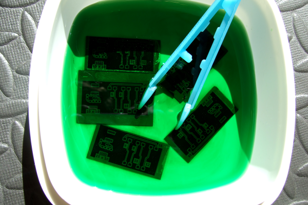
Copper Be Gone: The Chemistry Behind PCB Etching

For a lot of reasons, home etching of PCBs is somewhat of a dying art. The main reason is the rise of quick-turn PCB fabrication services, of course; when you can send your Gerbers off and receive back a box with a dozen or so professionally made PCBs for a couple of bucks, why would you want to mess with etching your own?

Convenience and cost aside, there are a ton of valid reasons to spin up your own boards, ranging from not having to wait for shipping to just wanting to control the process yourself. Whichever camp you’re in, though, it pays to know what’s going on when your plain copper-clad board, adorned with your precious artwork, slips into the etching tank and becomes a printed circuit board. What exactly is going on in there to remove the copper? And how does the etching method affect the final product? Let’s take a look at a few of the more popular etching methods to understand the chemistry behind your boards.

Continue reading “Copper Be Gone: The Chemistry Behind PCB Etching”

Harmonic Drive Uses Compliant Mechanism To Slim Down

[Levi Janssen] has a secret: he doesn’t like harmonic drives. But rather than abandon the torque-amplifying transmission completely, he decided to see about improving them using 3D-printed compliant mechanisms.

For the uninitiated, harmonic drives, also known as strain-wave gears, are a compact, high-torque gearbox that has become popular with “robotic dog” makers and other roboticists. The idea is to have a rigid, internally-toothed outer ring nested around an externally-toothed, flexible cup. A wave generator rotates within the inside cup, stretching it so that it meshes with the outer ring. The two gears differ by only a couple of teeth, meaning that very high gear ratios can be achieved, which makes them great for the joints of robot legs.

[Levi]’s problem with the harmonic drive is that due to the depth of the flexible spline cup, compactness is not among its virtues. His idea is to couple the flex spline to the output of the drive through a flat spring, one that allows flexion as the wave generator rotates but transmits torque efficiently. The entire prototype is 3D-printed, except for the wave generator bearings and stepper motor, and put to the test.

As the video below shows after the excellent introduction to harmonic drives, the concept works, but it’s not without its limitations. Even lightly loaded, the drive made some unpleasant crunching sounds as the PLA springs gave out. We could easily see that being replaced with, say, a steel spring, either machined or cut on a water-jet machine. That might solve the most obvious problem and make [Levi]’s dream of a compact harmonic drive a reality. Of course, we have seen pretty compact strain-wave gears before.

Continue reading “Harmonic Drive Uses Compliant Mechanism To Slim Down”

Simple Demo Shows The Potential Of Magnetic Gears

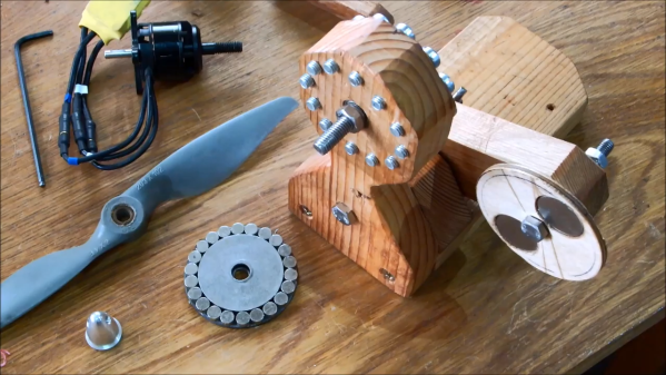
We’ve probably all used gears in our projects at one time or another, and even if we’re not familiar with the engineering details, the principles of transmitting torque through meshed teeth are pretty easy to understand. Magnetic gears, though, are a little less intuitive, which is why we appreciated stumbling upon this magnetic gear drivetrain demonstration project.

[William Fraser]’s demo may be simple, but it’s a great introduction to magnetic gearing. The stator is a block of wood with twelve bolts to act as pole pieces, closely spaced in a circle around a shaft. Both ends of the shaft have rotors, one with eleven pairs of neodymium magnets arranged in a circle with alternating polarity, and a pinion on the other side of the stator with a single pair of magnets. When the pinion is spun, the magnetic flux across the pole pieces forces the rotor to revolve in the opposite direction at a 12:1 ratio.

Watching the video below, it would be easy to assume such an arrangement would only work for low torque applications, but [William] demonstrated that the system could take a significant load before clutching out. That could even be a feature for some applications. We’ve got an “Ask Hackaday” article on magnetic gears if you want to dive a little deeper and see what these interesting mechanisms are good for.

Continue reading “Simple Demo Shows The Potential Of Magnetic Gears”

Cheap PSoC Enables Electrochemistry Research

You may think electrochemistry sounds like an esoteric field where lab-coated scientists labor away over sophisticated instruments and publish papers that only other electrochemists could love. And you’d be right, but only partially, because electrochemistry touches almost everything in modern life. For proof of that look no further than your nearest pocket, assuming that’s where you keep your smartphone and the electrochemical cell that powers it.

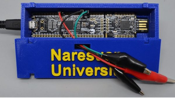
Electrochemistry is the study of the electrical properties of chemical reactions and does indeed need sophisticated instrumentation. That doesn’t mean the instruments have to break the grant budget, though, as [Kyle Lopin] shows with this dead-simple potentiostat built with one chip and one capacitor. A potentiostat controls the voltage on an electrode in an electrochemical cell. Such cells have three electrodes — a working electrode, a reference electrode, and a counter electrode. The flow of electrons between these electrodes and through the solutions under study reveal important properties about the reduction and oxidation states of the reaction. Rather than connect his cell to an expensive potentiostat, [Kyle] used a Cypress programmable system-on-chip development board to do everything. All that’s needed is to plug the PSoC into a USB port for programming, connect the electrodes to GPIO pins, and optionally add a 100 nF capacitor to improve the onboard DAC’s accuracy. The video below covers the whole process, albeit with a barely audible voiceover.

Still not sure about electrochemistry? Check out this 2018 Hackaday Prize entry that uses the electrochemistry of life to bring cell phones back to life.

Continue reading “Cheap PSoC Enables Electrochemistry Research”

Have Chainsaw, Will Travel

What’s the worst thing that could happen if you strapped a chainsaw motor to a tricycle? Turns out the worst that happened to [ThisDustin] and his friends is that it turned out hilariously awesome.

This aptly-named ‘chainsawtrike’ isn’t much in the way of comfort, so a pair of foot pegs had to be welded onto the front forks, along with a mount for the chainsaw motor. The rear axle had to be replaced with 5/8″ keyed stock, trimmed to fit the trike wheel and secured with keyed hubs. [ThisDustin] and crew also needed an intermediate sprocket to act as a reduction gear.

After a test that saw the chain jump off the sprockets and working out a few kinks — like the ability to turn — the chainsawtrike  can haul around its rider at a pretty decent clip. Check out the video of it in action after the break.

Continue reading “Have Chainsaw, Will Travel”

Customize Your Ratios With A 3D-Printed Gearbox

Small DC motors are easy to find — you can harvest dozens from old printers and copiers. You might even get a few with decent gearboxes too. But will you get exactly the motor with exactly the gearing your project needs? Unlikely, but you can always just print a gearbox to get exactly what you need.

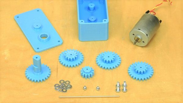
There’s nothing fancy about [fortzero]’s gearboxes. The motors are junk bin specials, and the gears are all simple spur gears 3D-printed from PLA. There are four gears in the train, each with a 2:1 reduction, giving a 16:1 overall ratio. The gears ride on brass shafts that are press-fit into the housing, and there’s not a bearing in sight — just a few washers to keep the gears spaced apart and plenty of grease. Despite the simplicity, the gearboxes turned out to be pretty capable, lifting a 3.5 kg load. The design files are available and should make it easy for you to get just the ratio you want for the motor you have.

Of course more complicated gearboxes are possible with a 3D printer, including a split-harmonic planetary gear, or a strain wave gear using a timing belt. No 3D printer? No problem! Just build a LEGO gearbox.

Continue reading “Customize Your Ratios With A 3D-Printed Gearbox”