Nexus 5X Phone Resurrected By The Oven

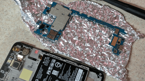
Warranty shmarranty — toss the phone in the oven! There’s apparently a problem with the assembly of the Nexus 5X smartphones, and it looks like it is due to faulty BGA chip soldering. LG USA has had enough problems with the phone that they may not even have enough parts or new units to fix it, so they’re offering a refund. But we all know how it is to get attached to a device, right?

So [Alex] disassembled his beloved phone, pulled out the board in question, and gave it the XBox Red Ring Of Death treatment. He placed the board on some insulating aluminum foil, and baked it for six and a half minutes. Season with lemon and pepper, and serve! We’re honestly surprised that sticking the affected board into the oven at 195° C / 390° F for a few minutes would work at all. Isn’t that a low temperature for soldering, especially with a lead-free mix? Could it have been a problem with humidity after all? Continue reading “Nexus 5X Phone Resurrected By The Oven”

Reflow Soldering At Another Level

We’re used to reflow soldering of our PCBs at the hacker level, for quite a few years people have been reflowing with toaster ovens, skillets, and similar pieces of domestic equipment and equipping them with temperature controllers and timers. We take one or two boards, screen print a layer of solder paste on the pads by using a stencil, and place our surface-mount components with a pair of tweezers before putting them in the oven. It’s a process that requires  care and attention, but it’s fairly straightforward once mastered and we can create small runs of high quality boards.

But what about the same process at a professional level, what do you do when your board isn’t a matchbox-sized panel from OSH Park with less than 50 or so parts but a densely-packed multilayer board  about the size of a small tablet computer and with many hundreds of parts? In theory the same process of screen print and pick and place applies, but in practice to achieve a succesful result a lot more care and planning has to go into the process.

This is being written the morning after a marathon session encompassing all of the working day and half of the night. I was hand-stuffing a row of large high-density boards with components ranging from 0402 passives to large QFPs and everything else in between. I can’t describe the board in question because it is a commercially sensitive prototype for the industrial customer of the friend I was putting in the day’s work for, but it’s worth going through the minutiae of successfully assembling a small batch of prototypes at this level. Apologies then, any pictures will be rather generic.

Continue reading “Reflow Soldering At Another Level”

Halogen Lamp Abused For Desoldering

[Moony] thought that it was unconscionable that IR soldering stations sell for a few hundred Euros. After all, they’re nothing more than a glorified halogen lightbulb with a fancy IR-pass filter on them. Professional versions use 100 W 12 V DC bulbs, though, and that’s a lot of current. [Moony] tried with a plain-old 100 W halogen lightbulb. Perhaps unsurprisingly, it worked just fine. Holding the reflector-backed halogen spotlight bulb close to circuit boards allows one to pull BGAs and other ornery chips off after a few minutes. Voila.

[Moony] reasons that the IR filter is a waste anyway, since the luminous efficiency of halogen lights is so low: around 3.5%. And that means 96.5% heat! But there’s still a lot of light streaming out into a very small area, so if you’re going to look at the board as you de-solder, you’re really going to need a pair of welding goggles. Without, you’ll have a very hard time seeing your work at best, and might actually do long-term damage to your retinas.

So the next time you’re feeling jealous of those rework factory workers with their fancy IR soldering stations, head on down to the hardware store, pick up a gooseneck lamp, a 100 W halogen spotlight, and some welding goggles. And maybe a fire brick. You really don’t want your desk going up in flames.

We love make-do hacks, but we love doing it right, too. Just watch [Bil Herd] extol the virtues of a real IR desoldering station. And then giggle as you do the same thing with a few-dollar halogen bulb.

Continue reading “Halogen Lamp Abused For Desoldering”

No-Etch Circuit Board Printing

If you’ve ever tried to build a printed circuit board from home, you know how much of a pain it can be. There are buckets of acid to lug around, lots of waiting and frustration, and often times the quality of the circuits that can be made traditionally with a home setup isn’t that great in the end. Luckily, [Rich] has come up with a way that eliminates multiple prints and the acid needed for etching.

His process involves using a laser printer (as opposed to an inkjet printer, as is tradition) to get a layer of silver adhesive to stick to a piece of paper. The silver adheres to the toner like glitter sticks to Elmer’s glue, and allows a single pass of a laser printer to make a reliable circuit. From there, the paper can be fastened to something more solid, and components can be reflow soldered to it.

[Rich] does post several warnings about this method though. The silver is likely not healthy, so avoid contact with it, and when it’s applied to the toner an indeterminate brown smoke is released, which is also likely not healthy. Warnings aside, though, this is a great method for making home-made PCBs, especially if you don’t want tubs of acid lying around the house, however useful.

Thanks to [Chris] for the tip!

Continue reading “No-Etch Circuit Board Printing”

Blowtorch SMD Reflow

result[whitequark] has been experimenting with a blowtorch for SMD reflow. Having just moved 8,000 km [whitequark] was stuck without any of the usual reflow tools. They did however have a blowtorch handy, and gave it a go.

When [whitequark] mentioned attempts on Twitter, we figured the results would mostly involve charred PCBs, smoke-filled rooms, and a possible trip to the local hospital. But [whitequark] is more sensible than we are, and by carefully monitoring the temperature and gauging the distance was able to get pretty decent results.

[whitequark]’s made a couple of further attempts and has had varying results. Overall, I’m not sure it’s a technique that I’m interested in trying myself, but it goes to show that in a pinch, a hacker will always find a creative way to get the job done.

Almost Fail Of The Week: Doing Surface Mount Reflow Wrong In Every Possible Way And Still Succeeding

Sometimes the best way to learn is from the success of others. Sometimes failure is the best teacher. In this case we are learning from [Tim Trzepacz]’s successive failures in his attempt to solder one board to another using a reflow oven. They somehow cancelled each other out, and he ended up with a working board. For those of you who have used a reflow oven, there will be eye rolling.

[Tim]’s first mistake was to use regular solder instead of paste. We can see how he got there logically; if you hand solder an SMD you melt solder onto the pads first to make it easier. However, the result was that he had two boards that wouldn’t sit flat on each other thanks to the globs of solder on the pads.

Not to be deterred, he laid the boards on top of each other and warmed up the oven to a toasty 650 degrees. Well, not quite. The dang oven didn’t turn to eleven, so he figured 500 would probably work too. Missing the hint entirely, he let his board bake in a nearly 1000F oven until he noticed some smoke which, he intuitively knew, definitely shouldn’t be happening.

The board was blackening, the solder mask was literally bubbling off the substrate, people were coming over to see the show, and he decided success was still possible. He clamped the heated boards together with a binder clip until they cooled. Someone gave him a lesson on reflow, presumably listened to through reddening ears.

Ashamed and defeated, he went home. However, there was a question in his mind. Sure it looks bad, but is it possible that the board actually works? After a quick test, the answer was yes. It loaded some code and an time later he was happily hacking away. Go figure.

Tools Of The Trade – Inspection

In the last episode, we put our circuit boards through the reflow process. Unfortunately, it’s not 100% accurate, and there are often problems that can occur that need to be detected and fixed. That’s what the inspection step is for. One could insert an inspection step after paste, after placement, and after reflow, but the first two are icing on the cake — the phase where most mistakes can be caught is after reflow.

There are a number of problems typical with a surface mount reflow process: Continue reading “Tools Of The Trade – Inspection”