No-Etch Circuit Board Printing

If you’ve ever tried to build a printed circuit board from home, you know how much of a pain it can be. There are buckets of acid to lug around, lots of waiting and frustration, and often times the quality of the circuits that can be made traditionally with a home setup isn’t that great in the end. Luckily, [Rich] has come up with a way that eliminates multiple prints and the acid needed for etching.

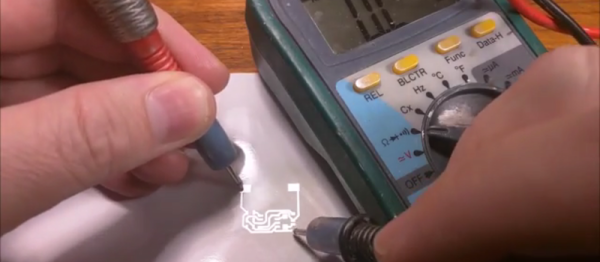
His process involves using a laser printer (as opposed to an inkjet printer, as is tradition) to get a layer of silver adhesive to stick to a piece of paper. The silver adheres to the toner like glitter sticks to Elmer’s glue, and allows a single pass of a laser printer to make a reliable circuit. From there, the paper can be fastened to something more solid, and components can be reflow soldered to it.

[Rich] does post several warnings about this method though. The silver is likely not healthy, so avoid contact with it, and when it’s applied to the toner an indeterminate brown smoke is released, which is also likely not healthy. Warnings aside, though, this is a great method for making home-made PCBs, especially if you don’t want tubs of acid lying around the house, however useful.

Thanks to [Chris] for the tip!
Continue reading “No-Etch Circuit Board Printing” →

Blowtorch SMD Reflow

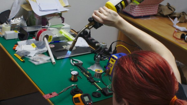
result[whitequark] has been experimenting with a blowtorch for SMD reflow. Having just moved 8,000 km [whitequark] was stuck without any of the usual reflow tools. They did however have a blowtorch handy, and gave it a go.
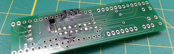
When [whitequark] mentioned attempts on Twitter, we figured the results would mostly involve charred PCBs, smoke-filled rooms, and a possible trip to the local hospital. But [whitequark] is more sensible than we are, and by carefully monitoring the temperature and gauging the distance was able to get pretty decent results.

[whitequark]’s made a couple of further attempts and has had varying results. Overall, I’m not sure it’s a technique that I’m interested in trying myself, but it goes to show that in a pinch, a hacker will always find a creative way to get the job done.

Almost Fail Of The Week: Doing Surface Mount Reflow Wrong In Every Possible Way And Still Succeeding

Sometimes the best way to learn is from the success of others. Sometimes failure is the best teacher. In this case we are learning from [Tim Trzepacz]’s successive failures in his attempt to solder one board to another using a reflow oven. They somehow cancelled each other out, and he ended up with a working board. For those of you who have used a reflow oven, there will be eye rolling.

[Tim]’s first mistake was to use regular solder instead of paste. We can see how he got there logically; if you hand solder an SMD you melt solder onto the pads first to make it easier. However, the result was that he had two boards that wouldn’t sit flat on each other thanks to the globs of solder on the pads.

Not to be deterred, he laid the boards on top of each other and warmed up the oven to a toasty 650 degrees. Well, not quite. The dang oven didn’t turn to eleven, so he figured 500 would probably work too. Missing the hint entirely, he let his board bake in a nearly 1000F oven until he noticed some smoke which, he intuitively knew, definitely shouldn’t be happening.

The board was blackening, the solder mask was literally bubbling off the substrate, people were coming over to see the show, and he decided success was still possible. He clamped the heated boards together with a binder clip until they cooled. Someone gave him a lesson on reflow, presumably listened to through reddening ears.

Ashamed and defeated, he went home. However, there was a question in his mind. Sure it looks bad, but is it possible that the board actually works? After a quick test, the answer was yes. It loaded some code and an time later he was happily hacking away. Go figure.

Tools Of The Trade – Inspection

In the last episode, we put our circuit boards through the reflow process. Unfortunately, it’s not 100% accurate, and there are often problems that can occur that need to be detected and fixed. That’s what the inspection step is for. One could insert an inspection step after paste, after placement, and after reflow, but the first two are icing on the cake — the phase where most mistakes can be caught is after reflow.

There are a number of problems typical with a surface mount reflow process: Continue reading “Tools Of The Trade – Inspection” →

“I Can Reflow” Merit Badge

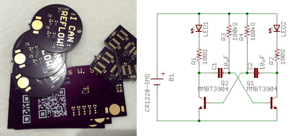
[Nick Sayer] can reflow, and he can prove it. He designed a simple blinking-LED circuit that uses SMD parts to, well, blink LEDs. That’s not the point, though. It’s designed to be a test platform for reflow soldering, and to use a minimum number of valuable parts. Plus, it says “I can reflow!” in exposed copper. What else do you want?

OK, as far as “proving it” goes, the badge isn’t 100% reliable — we hand-solder 0805 components all day long. But still, if you want to try your hand at reflowing a circuit board, and you don’t want to ruin a lot of expensive parts if you fail, something like this is a good idea.

The design is open, and it’s really the idea that’s the point here anyway. How about something that would be really onerous to hand-solder, but still cheap? We’re thinking a matrix of tiny LEDs and a shift register or something.

We just ran an article on a hand-soldering challenge board, this seems the perfect complement. Display both proudly on your desk and confound and amaze your coworkers!

Tools Of The Trade – Reflow

In our previous issues in this series on making circuit boards, we covered placing solder paste and placing components. Now it’s time to bake our cake!

There are a variety of methods for reflowing a circuit board, but they all rely on a single principle: heat up the solder paste (a mixture of flux and solder) until the flux burns off and the solder becomes liquid, and then cool it down. Accomplishing this once or twice is easy; once you’ve played with a hot plate you’ll swear off through hole. Scaling it up and doing it repeatedly with high yield is extremely challenging, though. Continue reading “Tools Of The Trade – Reflow” →

PTC Heaters For Reflow Soldering

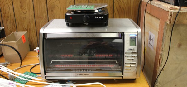
Reflow soldering – setting components on a PCB in blobs of solder paste and heating the whole assembly at once to melt all joints simultaneously – has been the subject of many ingenious hacks. Once it was the sole preserve of industrial users with specialist microprocessor-controlled ovens, now there are a myriad Arduino-controlled toaster ovens, hot air blowers, and hotplates that allow hackers and makers to get in on the reflow act too.

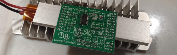
This morning a fresh idea in the reflow soldering arena has come our way. It’s not the most earth-shattering, but it does have some advantages so is worth a second look. [Analog Two] has successfully used a PTC heating element as a reflow soldering hotplate.

PTC heating elements are thermistors with a positive temperature coefficient. As their temperature rises, so does their electrical resistance. By careful selection of materials they can be manufactured with a sharp increase in resistance at a particular temperature. Thus when an electrical current is passed through them they heat up until they reach that temperature, then the current decreases as the resistance goes up, and they do not heat beyond that point. Thus as heaters they are intrinsically self-regulating. From our point of view they have another advantage, they are also cheap. Fitted as they are to thousands of domestic heating products they are readily available, indeed [Analog Two] found his on Amazon.

The heater chosen was a 200W 110V model with a temperature of 230 Celcius to match the solder he was using. They are also available for other mains voltages, and even at 12 and 24V for automotive applications. He reports that the time to reflow was about 90 seconds.

We’ve mentioned the advantages of this heater as its price and regulated temperature. Looking at the pictures though a disadvantage is its size. This is a reflow plate for small boards. There are larger PTC heater elements available though, it would be interesting to hear people’s experiences reflowing with them.

Hotplates for reflow soldering have featured before a few times here at Hackaday. We recently had this tiny plate, but we’ve also had a PID-controlled plate, and an Arduino-controlled domestic hotplate. We’re sure this is an avenue with further to go.