FabricKeyboard

FabricKeyboard Is Piano, Theremin And More

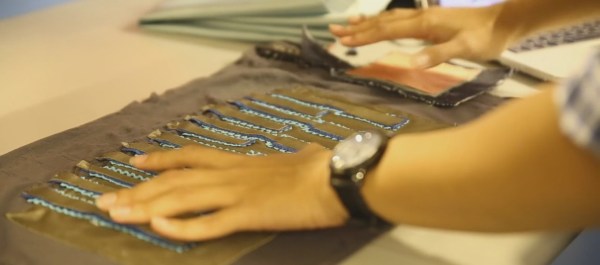
Two researchers of Responsive Environments, MIT Media Lab, have put to together a device that is an amazing array of musical instruments squeezed into one flexible package. Made using seven layers of fabrics with different electrical properties, the result can be played using touch, proximity, pressure, stretch, or with combinations of them. Using a fabric-based keyboard, ribbon-controller, and trackpad, it can be played as a one-octave keyboard, a theremin, and in ways that have no words, such as stretching while pressing keys. It can also be folded up and stuffed into a case along with your laptop, and care has even been taken to make it washable.

The FabricKeyboard layers

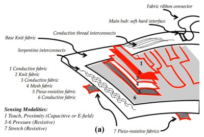
Layer one, the top layer, is a conductive fabric for detecting proximity and touch. The twelve keys can work independently with a MPR121 proximity touch controller or the controller can treat them all as one, extending the distance the hand can be and have it still work. Layer two is just a knit fabric but layers three to six detect pressure, consisting to two conductive layers with a mesh fabric and a piezo-resistive fabric in between. The piezo-resistive fabric is LTT-SPLA from eeonyx, a knit fabric coated with the conductive polymer, polypyrrole (PPy). Layer seven consists of two strips of knitted spandex fabric, also coated with PPy, and detects stretching. Two strips of this are sewn on the bottom, one horizontal and one vertical. You can see and hear the amazing sound this all produces in the video below.

Continue reading “FabricKeyboard Is Piano, Theremin And More”

Light Dimmer Shows How To Steal Power From AC Line

We see a lot of traffic on the tips line with projects that cover old ground but do so in an instructive way, giving us insight into the basics of electronics. Sure, commercial versions of this IR-controlled light dimmer have been available for decades. But seeing how one works might just help you design your Next Big Thing.

Like many electronic controls, the previous version of this hack required a connection to a neutral in addition to the hot. This version of the circuit relies on passing a small current through the light bulb the dimmer controls to avoid that extra connection. This design limits application to resistive loads like incandescent bulbs. But it’s still a cool circuit, and [Muris] goes into great detail explaining how it works.

We think the neatest bit is the power supply that actually shorts itself out to turn on the load. A PIC controls a triac connected across the supply by monitoring power line zero-crossing. The PIC controls dimming by delaying the time the triac fires, which trims the peaks off of the AC waveform. The PIC is powered by a large capacitor while the triac is conducting, preventing it from resetting until the circuit can start stealing power again. Pretty clever stuff, and a nice PCB design to boot.

Given the pace of technological and cultural change, it might be that [Muris]’ dimmer is already largely obsolete since it won’t work with CFLs or LEDs. But we can see other applications for non-switched mode transformerless power supplies. And then again, we reported on [Muris]’s original dimmer back in 2009, so the basic design has staying power.

How Not To Build A CPU Hand Warmer

Winter is coming, along with mittens, cold hands, snow, and jackets. Now that we’re all carrying around lithium batteries in our pocket, wouldn’t it be a great idea to build an electronic hand warmer? That’s what [GreatScott!] thought. To build his electronic hand warmer, he turned to the most effective and efficient way to turn electricity into heat: a ten-year-old AMD CPU.

Building an electronic hand warmer is exceptionally simple. All you need is a resistive heating element (like a resistor), a means to limit current (like a resistor), and a power supply (like a USB power bank). Connect these things together and you have a hand warmer that is either zero percent or one hundred percent efficient. We haven’t figured that last part out yet.

Because more power and more retro is more betterer, [GreatScott] pulled an AMD Sempron out of an old computer. Finding and reading data sheets is for wimps, apparently, so [GreatScott] just poked some pins with a variable power supply until the CPU was drawing about 500mA at 5V.

The video continues with some Arduino-based temperature measurement, finding some new pins to plug the power leads into, and securing all the wires on this heating element with hot glue. For anyone in the comments ready to say, ‘not a hack’, we assure you, this qualifies.

With the naive method of building a CPU hand warmer out of the way, here’s the pros and cons of this project, and how it can be made better. First off, using an old AMD processor was a great idea. These things are firestarters, and even though this processor preceded the 100+ W TDP AMD CPUs, it should work well enough.

That said, this is not how you waste power in a CPU. Ideally, the processor should do some work, with more active gates resulting in higher power consumption. If this were an exceptionally old processor, a good, simple option would be freerunning the chip, or having the CPU count up through its address space. This can be done by tying address lines low or high, depending on the chip. That’ll waste a significant amount of power. Randomly poking pins hoping for the right power consumption is not the way to get the most heat out of this CPU.

Of course, the above paragraph is just theory. The eating is in the pudding, or some other disfigured colloquialism, so here’s a quad-core 386 coffee warmer. This project from [magnustron] uses four 80386 CPUs powered via USB to make a nice desktop hotplate for your cuppa. Of course being powered by USB means there’s only 500mA to go around, and the ΔT is comparable to [GreatScott]’s AMD and hot glue hand warmer. Thus we get to the crux of the issue: 5V and 500mA isn’t very hot. Until cheap USB-C power banks, with ten or twelve Watts flood in from China, the idea of a USB powered heater is a fool’s errand. It does make for some great AMD firestarter jokes, though, so we have to give [GreatScott] credit for that.

Continue reading “How Not To Build A CPU Hand Warmer”

Ask Hackaday: DIY Handwriting Recognition

Computer handwriting recognition is very cool by itself, and it’s something that we’d like to incorporate into a project. So we went digging for hacker solutions, and along the way came up with an interesting bit of history and some great algorithms. We feel like we’ve got a good start on that front, but we’re stuck on the hardware tablet sensor itself. So in this Ask Hackaday, we’re going to make the case for why you could be using a tablet-like device for capturing user input or doing handwriting recognition, and then we’re going to ask if you know of any good DIY tablet designs to make it work.

Continue reading “Ask Hackaday: DIY Handwriting Recognition”

Enabling An Unused Touchscreen Overlay On A Consumer LCD

uncovering-an-unused-touchscreen-on-a-consumer-lcd

When [Andrei] first got his Raspberry Pi he wanted to make it a standalone computer right away. This means the normal input devices like a mouse and keyboard, but also some type of display. To avoid waiting for shipping he ended up using a cheap vehicle backup camera screen from the local big box store. It worked great, and recently he decided he would try to convert it to run off of 5V power to simplify his setup. While snooping around inside the device he discovered an unused resistive touch overlay and figured out how to get it to work.

What tipped him off is the small four-conductor connector which wasn’t hooked up to anything. He carefully soldered wires onto the flexible circuit traces, then generously covered them in hot glue to help prevent movement from breaking the rigid connection. To get this working you need to measure the resistance between the conductors. Most of the time we figure the RPi GPIO header can be used directly, but for this task an intermediary is necessary. [Andrei] went with a small Arduino clone board. A bit of trial and error was all it took to get the connections right and to iron out the code which translates the values into coordinates.

The Basics Of Reading Data From Resistive Touchscreens

[Chris] just posted his latest tutorial which shows you how to read position data from a resistive touchscreen. These devices are fairly simple, and since they’re used in a lot of consumer electronics you can pick one up for a few bucks. This looks like it is overstock for an old Palm device.

The interface is simple, there’s just four conductors on the tab at the top of the overlay. But connecting to these is a bit of an issue since you can’t really solder directly to them. [Chris] ended up using scotch-tape to hold wires in place, with a paperclip to keep them presses against the conductors. Those conductors are used in pairs, with a positive and negative lead for the X and Y axis. To take a measurement you use I/O pins to connect voltage and ground, then read the voltage that makes it to the gound side using an ADC. This works because the point that’s being pressed on the screen acts as a variable resistor for the circuit. Data for the two axes must be read in separate operations so that the positive voltages don’t interfere with each other.

The nice thing is that once you’ve got it working with a small screen it is easily scaled up. In fact, the 23″ touchscreen used on this Android hack is just another 4-wire resistive device.

You can see a video demonstration of [Chris’] test rig embedded after the break.

Continue reading “The Basics Of Reading Data From Resistive Touchscreens”

How To Build A 23″ Android Tablet

If you’re looking to build a really big Android tablet the trick is not to start from scratch. [Peter] pulled off a 23″ Android Tablet hack using a collection of easily acquired parts, leaving the hard work up to hardware that was designed to do it.

He didn’t really build a tablet, as much as he built a big touch-screen add-on for one. He already had a couple of inexpensive tablets on hand to play around with. One of them has an HDMI out port, which let him easily push the display onto a 23″ monitor. He knew the tablet was a 4-wire resistive touchscreen, but he didn’t know if other touchscreens with the same number of connectors and be directly swapped and still work. To test this, he cracked open a second tablet device and connected its touchscreen to the first one’s hardware. When he was met with success it was time to source a couple of 23″ touchscreen overlays to test with the external monitor. As you can see in the clip after the break, it works like a charm!

[Peter] was inspired to write about his experiences after seeing the 23″ Android tablet video in our recent links post.

Continue reading “How To Build A 23″ Android Tablet”