Blinktronicator’s POV Sends Our Eyebrows Rocketing Skyward

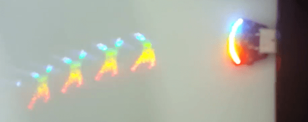
You think you’ve seen everything that there is to see regarding blinking LEDs and then a simple little trick proves you wrong. Our friend [Zach Fredin], aka [Zakqwy], added a pander mode to his blinky board which shows the Hackaday Jolly Wrencher in a Persistence of Vision mode. We love pandering, and obviously you just need to start the mode and wave the board back and forth. But in thinking the obvious you’d be wrong.

blinktronicator-board
Badass deadbug soldering to “fix” a mirrored shift register footprint

In the video after the break [Zach] demonstrates all the features of the blinktronicator and it’s recently finalized firmware. The tiny little board is a USB dongle featuring two buttons and an arc of sixteen LEDs in a rainbow of colors. When we say tiny, we mean it. Those LEDs are 0402 components and the board was small enough (and interesting enough) to receive an honorable mention in the Square Inch Project.

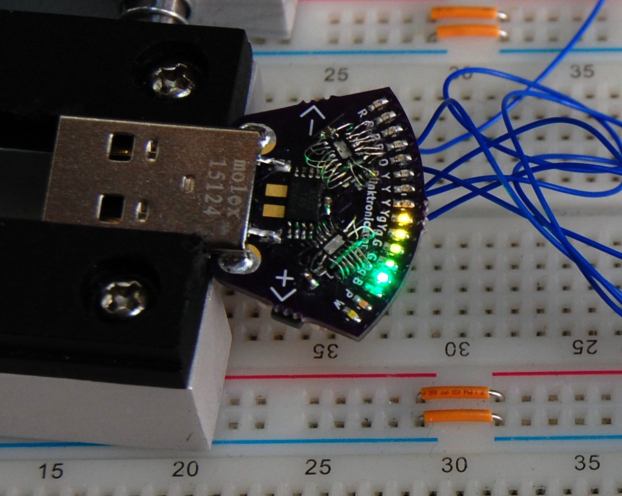
You would think that soldering all those LEDs by hand would be the trick, but [Zach] pulled off a much more difficult feat. Look closely at the image here (or click to embiggen). The two shift register footprints on the prototype were mirrored. He deadbug soldered each of them using — get this — the individual strands from some 28 AWG stranded wire. You sir, get the hardcore hand soldering badge and then some.

Okay, we’ll stop beating around the bush. The ATtiny45 on this board isn’t connected to the USB data lines, they’re only for power. That means, at its heart this is purely a blinking LED project, albeit one that uses the huge range of colors of the PICOLED family of parts. [Zach] did well with just two user inputs, but it’s the very simple POV party trick that really sucked us in. Instead of waving the board around, [Zach] uses a metal offset spatula as a mirror. Moving it back and forth unfolds the carefully timed flashes to draw your message in the air. Such a simple concept, but so satisfying to see it applied in a slightly different way.

Continue reading “Blinktronicator’s POV Sends Our Eyebrows Rocketing Skyward”

Hacking The IM-ME To Open Garages

If you have a wireless controlled garage door, a child’s toy can wirelessly open it in a few seconds. [Samy Kamkar] is a security researcher who likes to”think bad, do good”. He’s built OpenSesame, a device that can wirelessly open virtually any fixed-code garage door in seconds, exploiting a new attack he’s discovered in wireless fixed-pin devices, using the Mattel IM-ME toy.

The exploit works only on a gate or garage which uses “fixed codes”. To prevent this type of attack, all you need to do is to upgrade to a system which uses rolling codes, hopping codes, Security+ or Intellicode. These are not foolproof from attack, but do prevent the OpenSesame attack along with other traditional brute forcing attacks. It seems there are at least a couple of vendors who still have such vulnerable products, as well as several more whose older versions are affected too.

Before you read further, a caveat – the code released by [Samy] is intentionally bricked to prevent it from being abused. It might work, but just not quite. If you are an expert in RF and microcontrollers, you could fix it, but then you wouldn’t need his help in the first place, would you?

The IM-ME is a defunct toy and Mattel no longer produces it, but it can be snagged from Amazon or eBay if you’re lucky. The Radica Girltech IM-ME texting toy has been extensively hacked and documented. Not surprising, since it sports a TI CC1110 sub-GHz RF chip, an LCD display, keyboard, backlight, and more.  A good start point is the GoodFET open-source JTAG adapter, followed by the work of [Travis Godspeed] , [Dave] and [Michael Ossmann].

One issue with fixed code systems is their limited key space. For example, a remote with 12 binary dip switches supports 12 bits of possible combinations. Since its binary and 12 bits long, that’s 2^12, which is 4096 possible combinations. With a bit of math, [Samy] shows that it takes 29 minutes to open an (8-12)-bit garage, assuming you know the frequency and baud rate, both of which are pretty common. If you have to attempt a few different frequencies and baud rates, then the time it takes is a multiple of 29 minutes. If you don’t transmit the codes multiple times, and remove the pauses in between codes, the whole exercise can be completed in 3 minutes.

The weak link in the hardware is how the shift registers which decode the received codes work. Each bit is loaded in the register sequentially, gradually moving as additional bits come in and push the previous ones. This, and using an algorithm [Samy] wrote based on the De Bruijn sequence, the whole brute force attack can be completed in just over 8 seconds. OpenSesame implements this algorithm to produce every possible overlapping sequence of 8-12 bits in the least amount of time.

You can take a look at understanding how the code works by checking it out on Github. [Samy] loves doing such investigative work – check out his combo lock code breaker we featured recently, the scary, keyboard sniffing wall wart and the SkyJack – a drone to hack all drones.

Continue reading “Hacking The IM-ME To Open Garages”

Logic Noise: Taming The Wild Shift Register

One of the best things about DIY synth building is that you can create devices that just don’t exist in the commercial marketplace. In this session, we’ll build a looper / sequencer the likes of which you may have never seen. And it’s groovy. Today we’ll also get back a little closer to the soul of the series. In this session, nothing is analog — this is pure Logic Noise.

The shift register is the centerpiece chip this session, and a great device in its own right. We’ve got a lot of ground to cover, so watch the teaser video and then let’s get going.

Continue reading “Logic Noise: Taming The Wild Shift Register”

An Experiment In Shift Registers And Multiplexed LEDs

[Kratz] is working on a WiFi controlled scoreboard, but before building the full-scale version, he thought it would be wise to test out the multiplexing technique for the display. The experiment worked, but unless this scoreboard is for a foosball table, he still has a lot of work ahead of him.

The design of this prototype display is pretty simple, with just two ‘595 shift registers feeding bits to the display. Sixteen NPN transistors are being used to sink and source current to the display. It’s a relatively simple circuit, allowing [Kratz] to fit nine seven-segment displays on a small board with only six wires – ground, two V+ for the logic and LEDs, clock, data, and latch – going to the microcontroller.

There were a few snags in the design; the data is clocked in on a rising edge, but an extra falling edge was required before latching. [Kratz] can’t figure out the reason for this, and it might just be a timing issue.

IP Tracker

An Arduino Device That Monitors Your External IP Address

[Bayres’] dad setup a webcam as a surveillance camera for a remote property. The only problem was that the only stable Internet connection they could get at this property was DSL. This meant that the external IP address of the webcam would change somewhat often; the needed a way to keep track of the external IP address whenever it changed. That’s when [Bayres] built a solution using Arduino and an Ethernet shield.

The main function of this device is to monitor the public IP address and report any changes. This is accomplished by first making a request to checkip.dyndns.org. This website simply reports your current public IP address. [Bayres] uses an Arduino library called Textfinder in order to search through the returned string and identify the IP address.

From there, the program compares this current value to the previous one. If there is any change, the program uses the Sendmail() function to reach out to an SMTP server and send an e-mail alert to [Beyres’] dad. The system also includes a small LCD. The Arduino outputs the current IP address to this display, making it easy to check up on the connection. The LCD is driven by 74HC595 shift register in order to conserve pins on the Arduino.

The system is also designed with a pretty slick setup interface. When it is booted, the user can enter a configuration menu via a Serial terminal. This setup menu allows the user to configure options such as SMTP server, email address, etc. These variables are then edited and can be committed to EEPROM as a more permanent storage solution. Whenever the system is booted, these values are read back out of the EEPROM and returned to their appropriate variables. This means you can reconfigure the device on the fly without having to edit the source code and re-upload.

Hackaday Links Column Banner

Hackaday Links: The Last One Of 2014

The guy behind the Microslice, a tiny Arduino-controlled laser cutter, has a new Kickstarter out. It’s called the Multibox PC, and it’s exactly what you need if you want to turn a Raspi, Banana Pi, HummingBoard, or Odroid U3 into an all-in-one desktop. 14″ 1366 x 768 LCD, and speakers turns dev boards into a respectable little Linux box.

If you’re learning to design schematics and lay out PCBs, you should really, really think about using KiCAD. It’s the future. However, Eagle is still popular and has many more tutorials. Here’s another. [Mushfiq] put together a series of tutorials for creating a library, designing a schematic, and doing the layout.

Another kickstarter wristwatch. But wait, this thing has a circular display. That’s really cool. It’s a 1.4″ 220×220 pixel, 262k color display. No, the display doesn’t use a polar coordinate system.

[Jari] wrote a digital logic simulator, Atanua, started selling licenses, and figured out it wasn’t worth developing on his own anymore. As promised, Atanua is now open source. If you want to look at the finances behind Atanua, here you go.

In 1970, you didn’t have a lot of options when it came to memory. One of the best options was Intel’s 1405 shift register – 512 bits of storage. Yes, shift registers as memory. [Ken Shirriff] got his hands on a memory board from a Datapoint 2200 terminal. Each of the display boards had 32 of these shift registers. Here’s what they look like on the inside

There’s a lot of talk about North Korean hackers, and a quick review of the yearly WordPress stats for Hackaday puts a tear in our eye. This year, there were fifty-four views from the Democratic People’s Republic of Korea. That’s just great. It’s awesome to see the hacker ethos make it to far-flung lands and through highly restricted firewalls. There’s still a long road ahead of us, though, and we’ll redouble our efforts on bringing the hacker mindset to Tuvalu and Saint Helena in the year 2015.

Fail Of The Week: Reset Issues With 595 And HD44780

fotw-reset-issues-595-character-lcd

We really like to see hardware hackers stepping out of the safe and polished boundaries of available Arduino libraries. One example of this is a project which [Matteo] thought worked: using a shift register to drive a character LCD. This can be a desirable way to do things, because it takes the GPIO usage down from six to just three connections. If you don’t remember seeing that one earlier this month take another look. The gist of it is that [Matteo] hacked one function in the LiquidCrystal library to make it happen.

What makes this a truly great fail is that the problem was not immediately apparent, and is difficult to reliably reproduce. The LCD is unstable depending on how the Arduino board is reset. When connecting the Arduino to a computer the screen doesn’t work until you press the reset button. But press the reset button repeatedly and you get a non-functional screen plus the gibberish seen above.

There’s not much to go on here, but we think it’ll be a lot of fun to state your theory on the malfunction and suggesting for testing/fixing the issue. This could be a lot of things, the controller on the display getting mixed-up, the 595 missing an edge (or something along those lines). Do you fix this with hardware (ie: capacitor to avoid voltage dip), a software issue (need a longer delay after startup), or a combination of the two?


2013-09-05-Hackaday-Fail-tips-tileFail of the Week is a Hackaday column which runs every Wednesday. Help keep the fun rolling by writing about your past failures and sending us a link to the story — or sending in links to fail write ups you find in your Internet travels.