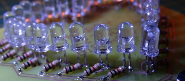
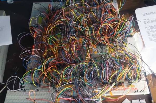
Hackaday Prize Entry: Pyrotechnics Sequencer With Wireless Control

[visualkev]’s friend was putting on his own fireworks show by lighting each one in turn, then running away. It occurred to [visualkev] that his friend wasn’t really enjoying the show himself because he was ducking for cover instead of watching the fun. Plus, it was kind of dangerous. Accordingly, he applied his hacker skills to the challenge by creating a custom fireworks sequencer.

He used a custom PCB from OSH Park with an ATMega328P controlling eight TPIC6C595 8-bit shift registers, which in turn trip the 64 relays connecting to the fireworks. A 5V regulator supplies the project from 5 5AA batteries, and he kept the wires neat with 8-wire ribbon cables.

Starting the sequence is a generic wireless remote — a cheapie from Walmart — allowing [visualkev]’s friend can launch the fireworks with one hand while working the barbecue tongs with the other.

Retro DEF CON Badge Made From ’80s Parts

DEF CON 25’s theme was retro-tech, and [xres0nance] wasn’t kidding around in the retro badge he built for the convention. The badge was mostly built out of actual parts from the ’80s and ’90s, including the perfboard from Radio Shack—even the wire and solder. Of the whole project just the resistors and 555 were modern parts, and that’s only because [xres0nance] ran out of time.

[xres0nance]  delayed working on the badge until his flight, throwing the parts in a box, and staggering to the airport in the midst of a “three-alarm hangover”. He designed the badge on the plane, downloading datasheets over in-flight WiFi and sketching out circuits in his notebook.

The display is from an old cell phone, and it uses a matrix of diodes to spell out DEFCON without the help of a microcontroller. Each letter is powered by a transistor, with specific pins blocked out to selectively power the segments. He used a shift register timed by a 555 to trigger each letter in turn, with the display scrolling the resulting message.

We publish a lot of posts about con badges. See our DEF CON 2015 badge summary for a bunch of badges that we encountered at in Vegas.

Glitchy Synthesizer Meets Honeycomb LED Matrix

Don’t watch [Jason Hotchkiss]’s video if flashing lights or bleepy-bloopy synthesizer noises give you seizures. Do watch, however, if you’re interested in a big honeycomb-shaped LED matrix being driven at audio frequencies through a dedicated square-wave synthesizer that’s built in.

The LED panel in question is housed in a snazzy laser-cut, honeycomb-shaped bezel: a nice change from the standard square in our opinion. The lights are 1/2 watt (whoa!) whites, and the rows and columns are driven by transistor drivers that are in turn controlled by shift registers. We’re not entirely sure how the matrix is driven — we’d love to see a circuit diagram — but it looks like it’s some kind of strange, non-scanning mode where all of the column and row drives are on at once. Whatever, it’s art.

And it’s driven by logic chips making audio-frequency square waves. Two of these are fed into an LFSR and into an R-2R DAC and then into the shift registers. The output is chaos, but the audio and the visuals do seem to influence each other. It’s an audio-visual embodiment of some of my wildest Logic Noise fantasies. Pretty cool. Enjoy the video.

Continue reading “Glitchy Synthesizer Meets Honeycomb LED Matrix”

A Very MIDI Christmas Lightshow

Christmas light displays winking and flashing in sync to music are a surefire way to rack up views on YouTube and annoy your neighbours. Inspired by one such video, [Akshay James] set up his own display and catalogued the process in this handy tutorial to get you started on your own for the next holiday season.

[James], using the digital audio workstation Studio One, took the MIDI data for the song ‘Carol of the Bells’ and used that as the light controller data for the project’s Arduino brain. Studio One sends out the song’s MIDI data, handled via the Hairless MIDI to serial bridge, to the Arduino which in turn sets the corresponding bit to on or off. That gets passed along to three 74HC595 shift registers — and their three respective relay boards — which finally trigger the relay for the string of lights.

From there, it’s a matter of wiring up the Arduino shift register boards, relays, and connecting the lights. Oh, and be sure to mount a speaker outdoors so passers-by can enjoy the music:

Continue reading “A Very MIDI Christmas Lightshow”

A Heart For His Girlfriend

[Decino] made a nice LED animated blinking heart box for his girlfriend. That’s a nice gesture, but more to the point here, it’s a nice entrée into the world of custom hardware. The project isn’t anything more than a home-etched PCB, a custom 3D-printed case, a mess of LEDs and current-limiting resistors, a shift register, and a microcontroller. (OK, we’re admittedly forgetting the Fifth Element.) The board is even single-sided with pretty wide traces. In short, it’s a great first project that ties together all of the basics without any parts left over. Oh, and did we mention Valentine’s day?

Once you’ve got these basics down, though, the world is your oyster. Building almost anything you need is just a matter of refining the process and practice. And if you’ve never played around with shift registers, a mega-blinker project like this is a great way to learn hands-on.

Not everything we write up on Hackaday has to be neural nets and JTAG ports. Sometimes a good beginner project that hits the fundamentals with no extra fat is just the ticket. What’s your favorite intro project?

Colorful, Touch-Sensitive Light Table Is Ready For Gaming

It’s an ambitious build for sure — you don’t start with $500 worth of wood if you don’t intend for the finished product to dazzle. And this 240-pixel touch-sensitive light box coffee table does indeed dazzle.

Sometimes when we see such builds as these, fit and finish take a back seat to function. [dasdingo89] bucks that trend with a nicely detailed build, starting with the choice of zebrawood for the table frame. The bold grain and the frosted glass top make for a handsome table, but what lurks beneath the glass is pretty special too. The 240 WS2812 modules live on custom PCBs, each thoughtfully provided with connectors for easy service. There’s also an IR transmitter-receiver pair on each board to detect when something is placed over the pixel. The pixel boards are connected to custom-built shift register boards for the touch sensors, and an Arduino with Bluetooth runs the whole thing. Right now the table just flashes and responds to hand gestures, but you can easily see this forming the basis of a beautiful Tetris or Pong table.

This build reminds us a little of this pressure-sensitive light floor we featured recently, which also has some gaming possibilities. Maybe [dasdingo89] and  [creed_bratton_] should compare notes and see who can come up with the best games for their platform.

[via r/DIY and a tip from emptycanister]

Run A RepRap On An ESP8266

What can’t the little $5 WiFi module do? Now that [lhartmann] has got an ESP8266 controlling the motors of a 3D printer, that’s one more item to check off the list.

What’s coolest about this project is the way that [lhartmann] does it. The tiny ESP8266 has nowhere near the required number of GPIO pins, the primary SPI is connected to the onboard flash memory, and the secondary SPI is poorly documented and almost nobody uses it. So, [lhartmann] chose to use the I2S outputs.

I2S is most often an audio protocol, so this might at first seem like a strange choice. Although I2S sounds like I2C, it’s really essentially an SPI protocol with a fourth wire that alternates to designate the right or left channel. It’s actually just perfect for sending 16×2 bits of data at high data rates.

[lhartmann] takes these 32 bits and feeds them into four shift registers, producing 32 outputs from just the four I2S data lines. That’s more than enough signals to run the stepper motors. And since it updates at 192 kHz sample rate, it’s plenty fast enough to drive them.

The other side benefit of this technique is that it can work on single-board computers with just a little bit of software. Programming very complicated stepper movements then becomes just a matter of generating the right “audio” file and playing it out. [lhartmann] demonstrated this earlier with an Orange Pi. That’s pretty cool, too.

The code for turning the ESP8266 and a short handful of 74HC595s into a 3D printer controller are up on GitHub, so go check it out.

Thanks [CNLohr] for the tip!