Art of 3D printer in the middle of printing a Hackaday Jolly Wrencher logo

3D Printering: Soldering A Heated Bed

There’s an old saying about something being a “drop in the ocean.” That’s how I felt faced with the prospect of replacing a 12 V heated bed on my printer with a new 24 V one. The old bed had a nice connector assembled from the factory, although I had replaced the cable long ago due to heating issues with that particular printer. The new bed, however, just had bare copper pads.

I’m no soldering novice: I made my first solder joint sometime in the early 1970s. So I felt up to the challenge, but I also knew I wouldn’t be able to use my usual Edsyn iron for a job like this. Since the heated bed is essentially a giant heatsink for these pads, I knew it would require the big guns. I dug out my old — and I mean super old — Weller 140 W soldering gun. Surely, that would do the trick, right?

Continue reading “3D Printering: Soldering A Heated Bed”

DIY Mechanical Flux Dispenser Syringe Has Fine Control

[Perinski]’s design for a mechanical flux dispenser uses some common hardware and a few 3D printed parts to create a syringe with fine control over just how much of the thick stuff gets deposited. The design is slick, and there’s a full parts list to accompany the printed pieces. [Perinski] even has some useful tips on how to most effectively get flux into 5 mL syringes without making a mess, which is a welcome bit of advice.

There is also a separate companion design for a magnetic syringe cap. Not only does it have an O-ring to keep things sealed and clean, but the tip of the cap has a magnet embedded into it, so that it can be stowed somewhere safe while the dispenser is in use, and doesn’t clutter the workspace.

This is all a very interesting departure from the design of most syringe dispensers for goopy materials, which tend to depend on some kind of pneumatic action. Even so, we’ve also seen that it’s possible to have a compact DIY pneumatic dispenser that doesn’t require a bulky compressor.

If you can’t quite figure out how the ergonomics of [Perinski]’s design are intended to work one-handed, you’re not alone. One holds the syringe in their hand, and turns the large dial in small increments with a thumb to control extrusion. [Perinski] demonstrates it close-up around the 4:50 mark, but if you have a few minutes it is worth watching the entire video, embedded below.

Continue reading “DIY Mechanical Flux Dispenser Syringe Has Fine Control”

Streamline Your SMD Assembly Process With 3D-Printed Jigs

Your brand-new PCBs just showed up, and this time you even remembered to order a stencil. You lay the stencil on one of the boards, hold it down with one hand, and use the other to wipe some solder paste across…. and the stencil shifts, making a mess and smearing paste across the board. Wash, rinse (with some IPA, of course), repeat, and hope it’ll work better on the next try.

openscad window
A PCB jig generated by OpenSCAD

Maybe it’s time to try Stencilframer, a 3D-printable jig generator created by [Igor]. This incredibly useful tool takes either a set of gerbers or a KiCad PCB file and generates 3D models of a jig and a frame to securely hold the board and associated stencil. The tool itself is a Python script that uses OpenSCAD for all 3D geometry generation. From there, it’s a simple matter to throw the jig and frame models on a 3D printer and voilà!– perfectly-aligned stencils, every time.

This is a seriously brilliant script. Anyone whose gone through the frustration of trying to align a stencil by hand should be jumping at the opportunity to try this out on their next build. It could even be paired with an Open Reflow hot plate for a fully open-source PCB assembly workflow.

Continue reading “Streamline Your SMD Assembly Process With 3D-Printed Jigs”

Nifty Chip Adapter Does The Impossible

The semiconductor shortage has curtailed the choices available to designers and caused some inventive solutions to be found, but the one used by [djzc] is probably the most inventive we’ve yet seen. The footprint trap, when a board is designed for one footprint but shortages mean the part is only available in another, has caught out many an engineer this year. In this case an FTDI chip had been designed with a PCB footprint for a QFN package when the only chip to be found was a QFP from a breakout board.

The three boards which make up the adaptor
The three boards which make up the adapter

For those unfamiliar with semiconductor packaging, a QFN and QFP share a very similar epoxy package, but the QFN has its pins on the underside flush with the epoxy and the QFP has them splayed out sideways. A QFP is relatively straightforward to hand-solder so it’s likely we’ll have seen more of them than QFNs on these pages.

There is no chance for a QFP to be soldered directly to a QFN footprint, so what’s to be done? The solution is an extremely inventive one, a two-PCB sandwich bridging the two. A lower PCB is made of thick material and mirrors the QFN footprint above the level of the surrounding components, while the upper one has the QFN on its lower side and a QFP on its upper. When they are joined together they form an inverted top-hat structure with a QFN footprint below and a QFP footprint on top. Difficult to solder in place, but the result is a QFP footprint to which the chip can be attached. We like it, it’s much more elegant than elite dead-bug soldering!

an up-close of the PCB hotplate

Using A PCB To Reflow PCBs – Take 2!

It’s not too hard to make your electronics project get warm. Design your traces too small, accidentally short the battery inputs together, maybe reverse the voltage going to your MCU. We’ve all cooked a part or two over the years. But what about making a PCB that gets hot on purpose? That’s exactly what [Carl Bugeja] did in his second revision of a PCB hot plate, designed to reflow other PCBs.

[Carl’s] first attempt at making a hot plate yielded lukewarm results. The board, which was a single snaking trace on the top of an aluminum substrate, did heat up as it was supposed to. However, the thin substrate led to the hot plate massively warping as it heated up, reducing the contact against the boards being soldered. On top of that, the resistance was much greater than expected, resulting in much lower heat output.

The new revision of the board is on a thicker substrate with much thicker traces, reducing the resistance from 36 ohms on the previous design to just 1 ohm. The thicker substrate, paired with a newer design with fewer slots, made for a much sturdier surface that did not bend as it was heated.

Continue reading “Using A PCB To Reflow PCBs – Take 2!”

The interior of a failed boiler.

Fail Of The Week: Learning How Not To Silver Solder

Sure, there are subtleties, but by and large it’s pretty easy to pick up soldering skills with a little practice. But wait! Not all soldering is created equal, and as [Quinn Dunki] learned, silver soldering is far harder to get right.

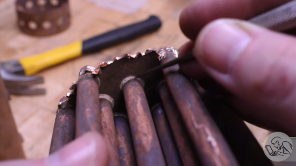
Granted, the job [Quinn] is working on is much more demanding than tacking some components to a PCB. She has been building a model steam engine, a task fit to put anyone’s machining skills to the test. And a steam engine needs a boiler, which is where the silver soldering comes in. As she explains in the video below, silver soldering, or “hard” soldering, uses solder that melts at a much higher temperature than “soft” solders like we’re used to in electronics. That’s a big advantage in the heat and pressure of a boiler, but it does pose some problems, many of which [Quinn] managed to discover as she tried to assemble her copper beast.

It turns out that heating a big hunk of copper evenly without burning off the flux actually isn’t that easy, though you can’t say she didn’t give it the old college try. In the process, she managed to share a number of tidbits that were really interesting, like the fact that drawing acetylene from a tank too fast can be dangerous, or that model steam boilers have to be certified by qualified inspectors. In the end, her boiler couldn’t be salvaged, and was put to the saw to determine the problem, which seems to be her initial choice of heating with oxyacetylene; after that initial failure, there was little she could do to save the boiler.

As [Quinn] says, “Failure is only failure if you don’t learn from it.” And so it may be a bit unfair to hang “Fail of the Week” on this one, but still — she has to go back to the beginning on the boiler. And we already know that model steam engines aren’t easy.

Continue reading “Fail Of The Week: Learning How Not To Silver Solder”

Practical Print Makes IPad A Magnificent Eye Piece

Be it the ever shrinking size of components, the miniscule size of the printing on such pieces, or the steady march of time that makes visits to the optometrist an annual ritual, many of us could use some assistance when things start getting fuzzy at the workbench. Arm-mounted LED magnifying lenses can be a handy helper. Zooming in on a macro photo on a smartphone is also a common option that we’ve used many times.

[Timo Birnschein] started down a similar path when he realized that his iPad Pro comes with an app called simply “Magnifier”. A 12” iPad isn’t exactly the most convenient device to hold while trying to solder small parts, so he spent some time designing and 3D printing a specialty iPad stand that he calls a “Quick and Dirty High Performance EE Microscope.” We call it a magnificent tool hack!

Rotating the iPad diagonally so that the camera is closest to the subject leaves plenty of room to work and makes great use of the available screen space. [Timo] reports that at 50% magnification the 12” screen makes even 0603 SMD parts easy to read. Now he rejoices to have more to do with his iPad than watching YouTube and reading Hackaday- although we don’t know why you couldn’t do both.

The STL files have been released on Thingverse for your experimentation. [Timo] notes that he’d like to add an LED ring to brighten things up, and a fume extractor to protect the delicate lens on the iPad. We have to wonder if some plastic wrap over the lens might produce the same effect at almost no cost. Whatever [Timo] decides to do, we’re sure it’ll be brilliant.

If you don’t have an iPad and a 3D printer, you might enjoy an earlier post that shows how you can use your phone as a microscope. If Lego and Raspberry Pi are your go-to parts, you can set your sights on this Lego/Pi/Arduino microscope.

Do you have your own preferred solution for seeing yourself through a hazy situation? Be sure to write it up, and then drop it in the Tip Line!