Sounds like somebody had a really bad day at work, as Western Digital reports that “factory contamination” caused a batch of flash memory chips to be spoiled. How much, you ask? Oh, only about 7 billion gigabytes! For those of you fond of SI prefixes, that’s 7 exabytes of storage; to put that into perspective, it’s seven times what Google used for Gmail storage in 2012, and enough to store approximately 1.69 trillion copies of Project Gutenberg’s ASCII King James Version Bible. Very few details were available other than the unspecified contamination of two factories, but this stands poised to cause problems with everything from flash drives to phones to SSDs, and will probably only worsen the ongoing chip shortage. And while we hate to be cynical, it’ll probably be prudent to watch out for any “too good to be true” deals on memory that pop up on eBay and Ali in the coming months.
soldering201 Articles
Another Neat General Purpose Soldering Iron Driver
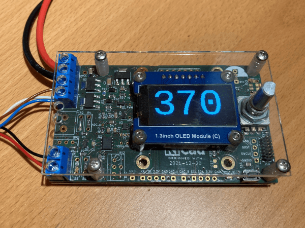
Over on Hackaday.io, user [Tomasz Jastrzebski] has designed a tidy-looking custom controller for driving temperature-controlled soldering irons. The design is intended to be general purpose, capable of operating with irons rated for different voltages and probe type, be they thermocouple- or thermistor-based. Rather than integrating a power supply, this is handled by an external unit, giving the possibility of feeding this from a variety of sources that are not necessarily tied to the grid.
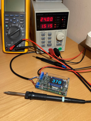
Hardware-wise, we’ve got the ubiquitous STM32 microcontroller in charge of the show, with a nice front end based on the INA823 instrumentation amplifier, referenced to a REF2030 precision voltage source. The input stage is configured as a versatile Wheatstone bridge input circuit, giving plenty of scope for tweaking.
There are a few extra features in the design that aren’t necessarily needed for a soldering iron driver, such as RTC support, complete with supercapacitor backup, but then this doesn’t have to drive a soldering iron, it could drive any DC heater with temperature feedback. With a change in firmware, this could serve other tasks. One potential feature that springs to mind — have the unit automatically power down at a certain time of day in case it was left on accidentally.
The schematic has a lot of relevant detail — in that many parts have a good list of alternatives, presumably because of the semiconductor shortages — which is a good habit to get into if you ask us. Many of us involved with manufacturing have been doing this for years, as it makes sense to give the assembly house the extra options, but this really is basically mandatory practice now.
Firmware for the STM32G0 series microcontroller is based on the STM32 HAL, keeping it simple, with a Visual Studio Code project provided for your convenience. All hardware (KiCAD) and firmware can be found on the project GitHub.
We’ve seen a few projects like this over the years, like this Really Universal Soldering Controller, a custom controller for JBC irons, and this great portable Arduino-based unit.

3D Printering: Soldering A Heated Bed
There’s an old saying about something being a “drop in the ocean.” That’s how I felt faced with the prospect of replacing a 12 V heated bed on my printer with a new 24 V one. The old bed had a nice connector assembled from the factory, although I had replaced the cable long ago due to heating issues with that particular printer. The new bed, however, just had bare copper pads.
I’m no soldering novice: I made my first solder joint sometime in the early 1970s. So I felt up to the challenge, but I also knew I wouldn’t be able to use my usual Edsyn iron for a job like this. Since the heated bed is essentially a giant heatsink for these pads, I knew it would require the big guns. I dug out my old — and I mean super old — Weller 140 W soldering gun. Surely, that would do the trick, right?
DIY Mechanical Flux Dispenser Syringe Has Fine Control
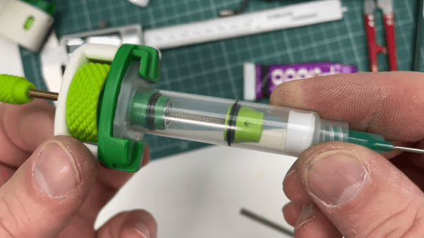
[Perinski]’s design for a mechanical flux dispenser uses some common hardware and a few 3D printed parts to create a syringe with fine control over just how much of the thick stuff gets deposited. The design is slick, and there’s a full parts list to accompany the printed pieces. [Perinski] even has some useful tips on how to most effectively get flux into 5 mL syringes without making a mess, which is a welcome bit of advice.
There is also a separate companion design for a magnetic syringe cap. Not only does it have an O-ring to keep things sealed and clean, but the tip of the cap has a magnet embedded into it, so that it can be stowed somewhere safe while the dispenser is in use, and doesn’t clutter the workspace.

This is all a very interesting departure from the design of most syringe dispensers for goopy materials, which tend to depend on some kind of pneumatic action. Even so, we’ve also seen that it’s possible to have a compact DIY pneumatic dispenser that doesn’t require a bulky compressor.
If you can’t quite figure out how the ergonomics of [Perinski]’s design are intended to work one-handed, you’re not alone. One holds the syringe in their hand, and turns the large dial in small increments with a thumb to control extrusion. [Perinski] demonstrates it close-up around the 4:50 mark, but if you have a few minutes it is worth watching the entire video, embedded below.
Continue reading “DIY Mechanical Flux Dispenser Syringe Has Fine Control”
Streamline Your SMD Assembly Process With 3D-Printed Jigs
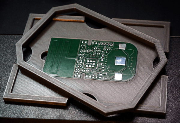
Your brand-new PCBs just showed up, and this time you even remembered to order a stencil. You lay the stencil on one of the boards, hold it down with one hand, and use the other to wipe some solder paste across…. and the stencil shifts, making a mess and smearing paste across the board. Wash, rinse (with some IPA, of course), repeat, and hope it’ll work better on the next try.

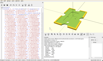
Maybe it’s time to try Stencilframer, a 3D-printable jig generator created by [Igor]. This incredibly useful tool takes either a set of gerbers or a KiCad PCB file and generates 3D models of a jig and a frame to securely hold the board and associated stencil. The tool itself is a Python script that uses OpenSCAD for all 3D geometry generation. From there, it’s a simple matter to throw the jig and frame models on a 3D printer and voilà!– perfectly-aligned stencils, every time.
This is a seriously brilliant script. Anyone whose gone through the frustration of trying to align a stencil by hand should be jumping at the opportunity to try this out on their next build. It could even be paired with an Open Reflow hot plate for a fully open-source PCB assembly workflow.
Continue reading “Streamline Your SMD Assembly Process With 3D-Printed Jigs”
Nifty Chip Adapter Does The Impossible
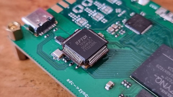
The semiconductor shortage has curtailed the choices available to designers and caused some inventive solutions to be found, but the one used by [djzc] is probably the most inventive we’ve yet seen. The footprint trap, when a board is designed for one footprint but shortages mean the part is only available in another, has caught out many an engineer this year. In this case an FTDI chip had been designed with a PCB footprint for a QFN package when the only chip to be found was a QFP from a breakout board.

For those unfamiliar with semiconductor packaging, a QFN and QFP share a very similar epoxy package, but the QFN has its pins on the underside flush with the epoxy and the QFP has them splayed out sideways. A QFP is relatively straightforward to hand-solder so it’s likely we’ll have seen more of them than QFNs on these pages.
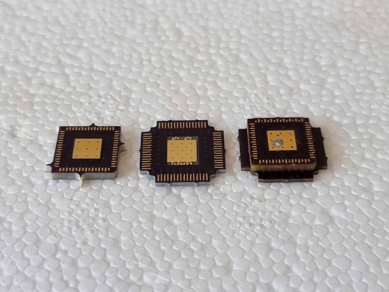
There is no chance for a QFP to be soldered directly to a QFN footprint, so what’s to be done? The solution is an extremely inventive one, a two-PCB sandwich bridging the two. A lower PCB is made of thick material and mirrors the QFN footprint above the level of the surrounding components, while the upper one has the QFN on its lower side and a QFP on its upper. When they are joined together they form an inverted top-hat structure with a QFN footprint below and a QFP footprint on top. Difficult to solder in place, but the result is a QFP footprint to which the chip can be attached. We like it, it’s much more elegant than elite dead-bug soldering!
Using A PCB To Reflow PCBs – Take 2!
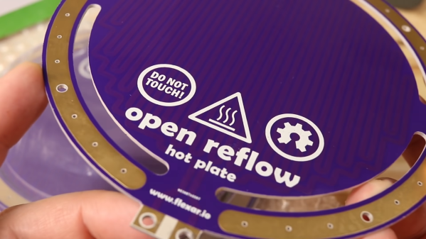
It’s not too hard to make your electronics project get warm. Design your traces too small, accidentally short the battery inputs together, maybe reverse the voltage going to your MCU. We’ve all cooked a part or two over the years. But what about making a PCB that gets hot on purpose? That’s exactly what [Carl Bugeja] did in his second revision of a PCB hot plate, designed to reflow other PCBs.
[Carl’s] first attempt at making a hot plate yielded lukewarm results. The board, which was a single snaking trace on the top of an aluminum substrate, did heat up as it was supposed to. However, the thin substrate led to the hot plate massively warping as it heated up, reducing the contact against the boards being soldered. On top of that, the resistance was much greater than expected, resulting in much lower heat output.
The new revision of the board is on a thicker substrate with much thicker traces, reducing the resistance from 36 ohms on the previous design to just 1 ohm. The thicker substrate, paired with a newer design with fewer slots, made for a much sturdier surface that did not bend as it was heated.