The Hackaday Prize Semifinalist Update

There are only a few more days until The Hackaday Prize semifinalists need to get everything ready for the great culling of really awesome projects by our fabulous team of judges. Here are a few projects that were updated recently, but for all the updates you can check out all the entries hustling to get everything done in time.


Replacing really, really small parts

acc
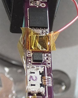
The NoteOn smartpen is a computer that fits inside a pen. Obviously, there are size limitations [Nick Ames] is dealing with, and when a component goes bad, that means board rework in some very cramped spaces. The latest problem was a defective accelerometer.

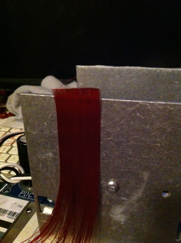
In a normal project, a little hot air and a pair of tweezers would be enough to remove the defective part and replace it. This is not the case with this smart pen. It’s a crowded layout, and 0402 resistors can easily disappear in a large solder glob.

[Nick] wrapped the closest parts to the defective accelerometer in Kapton tape. That seemed to be enough to shield it from his Aoyue 850 hot air gun. The new part was pre-tinned and placed back on the board with low air flow.

How to build a spectrometer

spec

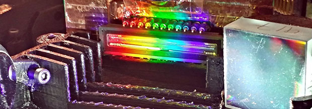
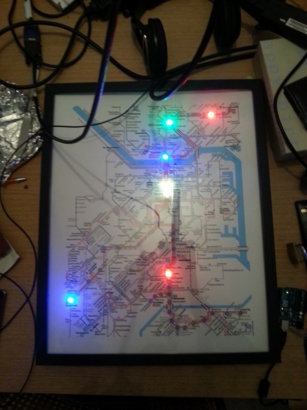
The RamanPi Spectrometer is seeing a lot of development. The 3D printed optics mount (think about that for a second) took somewhere between 12 and 18 hours to print. Once that was done and the parts were cleaned up, the mirrors, diffraction grating, and linear CCD were mounted in the enclosure. Judging from the output of the linear CCD, [fl@C@] is getting some good data with just this simple setup.

Curing resin and building PCBs

uv
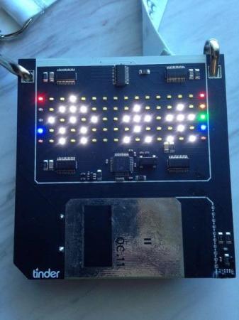
[Mario], the guy behind OpenExposer, the combination SLA printer, PCB exposer, and laser harp is chugging right along. He finished his first test print with a tilted bed and he has a few ideas on how to expose PCBs on his machine.

You don’t need props to test a quadcopter

blades
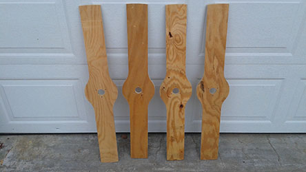
Goliath, the gas-powered quadcopter, had a few problems earlier this month. During its first hover test a blade caught a belt and bad things happened. [Peter] is testing out a belt guard and tensioner only this time he’s using plywood cutouts instead of custom fiberglass blades. Those blades are a work of art all by themselves and take a long time to make; far too much effort went into them to break in a simple motor test.

The internals of a home built 10 MHz frequency reference.

Low Cost Lab Frequency Reference

[Mark] wanted an accurate frequency reference for his electronics lab. He specified some requirements for the project, including portability, ability to work inside a building, and low cost. That ruled out GPS, cesium standard clocks, rubidium standard clocks, and left him looking for a low cost Oven Controlled Crystal Oscillator (OCXO).

The Low Cost 10 MHz Frequency Reference is based around a Morion OCXO. These Russian oscillators are available from eBay second hand at about $40 a pop. With a stability well within the requirements, [Mark] order a few.

The next step was to stick all the components in a box. The two OCXOs in the box need about 3 amps to heat up, which is provided by a 12 V PSU. For portability, a sealed lead acid battery was added. The front panel shows the supply voltages, switches between mains and battery supplies, and provides connectivity to the OCXOs.

Since OCXOs work by heating a crystal to a specific temperature, they can use quite a bit of power in the heating element. To increase battery life, a neoprene foam insulator was wrapped around the OCXOs.

For less than $100, this portable tool will aid in calibrating equipment or creating very accurate clocks.

Afroman Demonstrates Boost Converters

If you need to regulate your power input down to a reasonable voltage for a project, you reach for a switching regulator, or failing that, an inefficient linear regulator. What if you need to boost the voltage inside a project? It’s boost converter time, and Afrotechmods is here to show you how they work.

In its simplest form, a boost converter can be built from only an inductor, a diode, a capacitor, and a transistor. By switching the transistor on and off with varying duty cycles, energy is stored in the inductor, and then sent straight to the capacitor. Calculating the values for the duty cycle, frequency, inductor, and the other various parts of a boost converter means a whole bunch of math, but following the recommended layout in the datasheets for boost and switching converters is generally good enough.

boostconverter

[Afroman]’s example circuit for this tutorial is a simple boost converter built around an LT1370 switching regulator. In addition to that there’s also a small regulator, diode, a few big caps and resistors, and a pot for the feedback pin. This is all you need to build a simple boost converter, and the pot tied to the feedback pin varies the duty cycle of the regulator, changing the output voltage.

It’s an extremely efficient way to boost voltage, measured by [Afroman] at over 80%. It’s also exceptionally easy to build, with just a handful of parts soldered directly onto a piece of perfboard.

Video below.

Continue reading “Afroman Demonstrates Boost Converters”

30 Years Later TED Finds His Voice: A Commodore Story Part II

[Continued from 30 Years later TED finds his voice: A Commodore Story Part I]

Like parents standing on the porch waiting to see their children off to their first day of school we waited for what comes next in a release to production. Among our children: The C116 ($49 Sinclair killer), the C264 ($79 office computer), and the V364 – The computer with an interactive desktop that could speak (courtesy of [John Fegans] who gave us the lion’s share of what made the C64 software great).

Something happened then, and by something I mean nothing. Nothing happened. We waited to assist in production builds and stood ready to make engineering change notices, and yet nothing happened. It was around this time that [Mr. Jack Tramiel] had left the company, I know why he left but I can’t tell due to a promise I made. Sadly, without [Tramiel’s] vision and direction the new product releases pretty much stopped.

What happens when Marketing tries to design a computer: a TED in a C64 case known as a C16
What happens when Marketing tries to design a computer: a TED in a C64 case known as a C16.

Meanwhile in Marketing, someone came up with the idea to make the C264 more expensive so that they could then sell it for a prohibitively high price in. They changed the name, they told us to add chips, and they added software that (at best) wasn’t of interest to the users at that price. They wanted another C64, after all it had previously been the source of some success. Meanwhile the C116 and the V364 prototypes slowly melded into the random storage of a busy R&D lab. We literally didn’t notice what had happened; we were too busy arguing against abominations such as the C16 — a “creation” brought about by a shoving a TED board into a C64 case (the term inbred came to mind at the time).

Continue reading “30 Years Later TED Finds His Voice: A Commodore Story Part II”

An Electric Arc Printer For Rapid 3D Prototyping

Additive manufacturing, aka 3D printing, is able to produce wonderful and amazing objects in relatively short periods of time. Items are now being created in hours, not days, which is an extraordinary leap in technology. However, waiting for a 3D printer to complete its cycle is still a lot like watching paint dry. It takes way too long, and occasionally, time is of the essence when prototyping products for a client. Sometimes you just need it done now,…not a few hours from now.

[0n37w0] is hoping solve this problem by working on a way to ‘print’ 3D objects using arcs of electricity. We are still trying to wrap our heads around how this will work, but from the looks of it, arc printing “is done by completing an electrical current on an area of granulated metal thus heating the metal enough to form a bond to the structure being printed.

The printer is comprised of four main components (the print bed, the lifting device, the control box, and the granulated metal supply bin). The supply bin feeds granulated metal, possibly by vibration, onto the print bed. A lifting mechanism is then lowered within electrical contact and the printing begins. After each layer, the object is raised.

To find out more, check out the Hackaday.io project page.

The badge from Queercon 11 at Defcon

The Queercon 11 Badge

DEFCON is known for its unique badge designs, which have featured displays, radios, and tons of LEDs in the past. This year, there was another digital badge at DEFCON. The Queercon 11 badge featured an MSP430, a LED display, an IR interface, and an ISM band radio.

Queercon started off as a DEFCON party for LGBT hackers. Over the past eleven years they’ve run events at DEFCON including parties, mixers, and networking events. Over time the group has grown, become a non-profit, and provided a social network for LGBT people in tech. We must admit that they throw quite a good pool party.

This badge gave you points for meeting other people. When held near another QC11 badge, the IR link sends the identifier for each person. Both badges light up and display the other person’s name, and store the event. This process became known by a variety of colloquialisms, and “badginal intercourse” was a common occurrence at events.

The reader for Queercon 11 badges
The QC11 Badge Reader

The RF radio, implemented using a HopeRF RF69 module, shows how many people with QC11 badges are near you. A base station at events sends out data to give badges points for attendance. As points are accumulated, the rainbow LEDs on either side of the display light up.

At Queercon parties, a reader connected to a dumb terminal read data off the badges. It then shows who the badge has paired with, and what events its been to.

The hardware design and source code have all been released on the Queercon website. The full functionality is discussed in the README.

Subway radar

LEDs Turn This Paper Map Into A Tram Tracker

Public transit can be a wonderful thing. It can also be annoying if the trains are running behind schedule. These days, many public transit systems are connected to the Internet. This means you can check if your train will be on time at any moment using a computer or smart phone. [Christoph] wanted to take this concept one step further for the Devlol hackerspace is Linz, Austria, so he built himself an electronic tracking system (Google translate).

[Christoph] started with a printed paper map of the train system. This was placed inside what began as an ordinary picture frame. Then, [Christoph] strung together a series of BulletPixel2 LEDs in parallel. The BulletPixel2 LEDs are 8mm tri-color LEDs that also contain a small controller chip. This allows them to be controlled serially using just one wire. It’s similar to having an RGB LED strip, minus the actual strip. [Christoph] used 50 LEDs when all was said and done. The LEDs were mounted into the photo frame along the three main train lines; red, green, and blue. The color of the LED obviously corresponds to the color of the train line.

The train location data is pulled from the Internet using a Raspberry Pi. The information must be pulled constantly in order to keep the map accurate and up to date. The Raspberry Pi then communicates with an Arduino Uno, which is used to actually control the string of LEDs. The electronics can all be hidden behind the photo frame, out of sight. The final product is a slick “radar” for the local train system.