Push Button, Receive Bacon.

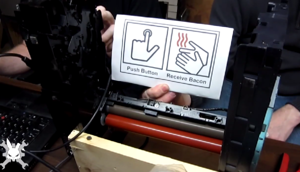
Members of the Rabbit Hole hackerspace spent the last weekend competing in The Deconstruction, a 48 hour hackathon competition. The hackerspace’s theme was “Light it up!”, so members created some awesome projects involving light. The star of the show was their bacon cooking machine. The Rabbit hole made the “Push Button. Receive Bacon” meme real.

A broken laser printer was gutted for its drive train and fuser assembly. Laser printer fusers are essentially hot rollers. The rollers melt toner and fuse it with paper as it passes through the printer. The heat in this case comes from a lamp inside the roller. That lamp also puts out plenty of light, which fit perfectly with the team’s theme.

The Rabbit Hole members wasn’t done though, they also built a pocket-sized infinity mirror from an empty Altoids tin. The bottom of the tin was cut out, and a mirror glued in. A filter from a broken projector made a perfect half silver mirror, and some LEDs completed the project.

The members also built a fandom art piece, consisting of 25 fans connected together in a skull shape. The eye and nose fans were lighted. When the fans were plugged in, they kicked for a few seconds before spinning up. Once they did spin though – there was a mighty wind in the Rabbit Hole.

Click past the break for The Rabbit Hole’s Deconstruction video!

Continue reading “Push Button, Receive Bacon.”

Interview With A Printer

The Hackaday European tour continues, this time in Prague with Josef Průša (Google translate), core developer in the RepRap project, feature at all the Maker Faires and cons, and creator of his namesake, the Prusa Mendel and i3 printers.

[Prusa]’s involvement with the RepRap project started with a RepRap Mendel, the second iteration of RepRap hardware, but the first popular and easy to build version. [Jo] found the Mendel rather difficult to build, so he loaded OpenSCAD and started to design his own version of the hardware. This version became the de facto standard RepRap for a few years, with many inspired by and derivative printers making their way to hackerspaces and workshops around the world.

The first Prusa printer, derived from the RepRap Mendel.

A few years ago, [Prusa] was one of the first to make a complete break with the traditional ‘threaded rod and nut’ construction of RepRaps with the introduction of the Prusa i3. This was the first model that had a metal plate as the frame, another feature that would be seen in dozens of other models. It’s not something that was without controversy, either; using a metal plate for the frame doesn’t allow for as much self-replication, something that’s a core value of the RepRap project. That didn’t matter to the community; the Prusa i3 or a similar design is the third most popular printer on 3Dhubs.

The first Prusa printer showing off its Makerbot heritage

What’s the future of the Prusa name? There is an i4 in the works, and I’m pretty sure that’s all I can tell you. Someone already bought the Prusai4 domain, so there may be a name change.

In the interview below, [Prusa] goes over his involvement with the RepRap project, his business, what he considers to be the latest advances in 3D printing for the past year, what the worst things about the 3D printing scene is (it’s Kickstarter), the state of the RepRap project, and thoughts on SLS, DLP, and SLA printing technologies. Video below.

Continue reading “Interview With A Printer”

Arduino Lithium Charger Shield

Programmable Lithium Charger Shield For Arduino

Surely you need yet another way to charge your lithium batteries—perhaps you can sate your desperation with this programmable multi (or single) cell lithium charger shield for the Arduino?! Okay, so you’re not hurting for another method of juicing up your batteries. If you’re a regular around these parts of the interwebs, you’ll recall the lithium charging guide and that rather incredible, near-encyclopedic rundown of both batteries and chargers, which likely kept your charging needs under control.

That said, this shield by Electro-Labs might be the perfect transition for the die-hard-‘duino fanatic looking to migrate to tougher projects. The build features an LCD and four-button interface to fiddle with settings, and is based around an LT1510 constant current/constant voltage charger IC. You can find the schematic, bill of materials, code, and PCB design on the Electro-Labs webpage, as well as a brief rundown explaining how the circuit works. Still want to add on the design? Throw in one of these Li-ion holders for quick battery swapping action.

[via Embedded Lab]

RTL SDR As A Spectrum Analyzer

RTL-SDR, the USB TV tuner turned software-defined radio is an amazing device, capable of listening to nearly anything from 25MHz to 1750MHz, fits in your pocket, and costs about $20. Even more astonishing is that it’s also a kinda-okay spectrum analyzer. [Kerry D. Wong] tested out one of these USB TV tuner, and the results are exactly what you would expect: it lacks a little precision, and sampling bandwidth is only a tiny bit terrible, but it does work.

A stock USB TV tuner doesn’t come with a connector that would normally be used for spectrum analysis. A BNC connector can be easily attached, as can a terminator to match the 75Ω impedance of the SDR. This isn’t really necessary; the frequencies being measured are low enough that you can get away without one.

As far as software goes, [Kerry] first pulled out the usual suspects of the SDR world; rtlsdr-scanner distorted the measured spectrum, as did a lot of other SDR receivers. Gqrx SDR was the first one that worked well, but the king of this repurposing of USB TV tuners was OSMOCOM. There’s a huge number of tools for spectrum analysis right out of the box with this package.

How did the RTL SDR fare as a spectrum analyzer? Feeding some stuff in from a signal generator, [Kerry] discovered the LO in the RTL SDR was off by a hair. Also, OSMOCOM only measures amplitude in dB, not the dBm found in every other spectrum analyzer ever made. By measuring a 0 dBm signal whatever value displayed can be shifted up or down.

So, does it work? Yes, it does. If, for some reason, you need a spectrum analyzer now, can you use this? Yep. Pretty cool.

Measuring The Length Of WS2812 Strips

[Tim] discovered a simple way to measure the length of WS2812 addressable LED strips from a microcontroller. This is great for any project that can have an arbitrary length of addressable LED strip attached to it.

The simplest (and perhaps most reliable) way to measure strip length is by feeding the serial output pin of the end of the strip back to the microcontroller. The microcontroller keeps clocking bits into the strip until it receives data from the end of the strip. [Tim] didn’t want to run an additional signal to the end of his strip, so he found another solution.

[Tim] used the ADC of his microcontroller (an ATtiny) to measure supply voltage droop as LEDs are turned on. Each LED draws around 60mA at full brightness, so [Tim] sequentially turned on each LED and watched the ADC for slight voltage changes. If the voltage changed, there must be an LED at that address. [Tim] does note that this method is extremely dependent on the power supply used and only works on short strips. Check out his blog post for more details.

Extreme Repair Of An All-in-One PC

While browsing a local auction site, [Viktor] found himself bidding on a beat up Lenovo A600 all-in-one PC. He bid around $50 and won. Then came the hard part – actually making the thing work. The front glass was cracked, but the LCD was thankfully unharmed. The heat pipes looked like they had been attacked with monkey wrenches. The superIO chip’s pins were mangled, and worst of all, the MXM video card was dead.

The first order of business was to fix the superIO chip’s pins and a few nearby discrete components which had been knocked off their pads. Once that was done, [Viktor] was actually able to get the computer to boot into Linux from a USB flash drive. The next step was bringing up the display. [Viktor] only needed a coding station, so in addition to being dead, the video accelerator on the MXM wasn’t very useful to him. The Lenovo’s motherboard was designed to support video on an MXM card or internal video. Switching over meant changing some driver settings and moving a few components, including a rather large LVDS connector for the display itself. A difficult task, compounded by the fact that [Viktor’s] soldering tools were a pair of soldering guns that would be better suited to fixing the bodywork on a ’57 Chevy. He was able to fashion a hot wire setup of sorts, and moved the connector over. When he was done, only one tiny solder bridge remained!

The end result is a new coding battle station for [Viktor] and a computer which was a basket case is saved from the landfill. If you like this hack, check out [Viktor’s] low power PSU, or his 1 wire network!

‘Nutclough’ Circuit Board Design Is Stylishly Amplified

Though there is nothing wrong with the raw functionality of a plain rectangular PCB, boards that work an edge of aesthetic flare into their layout leave a lasting impression on those who see them. This is the philosophy of circuit artist [Saar Drimer] of Boldport, and the reason why he was commissioned by Calrec Audio to create the look for their anniversary edition amplifier kit. We’ve seen project’s by [Saar] before and this ‘Nutclough18’ amplifier is another great example of his artistic handy work.

nutclough2
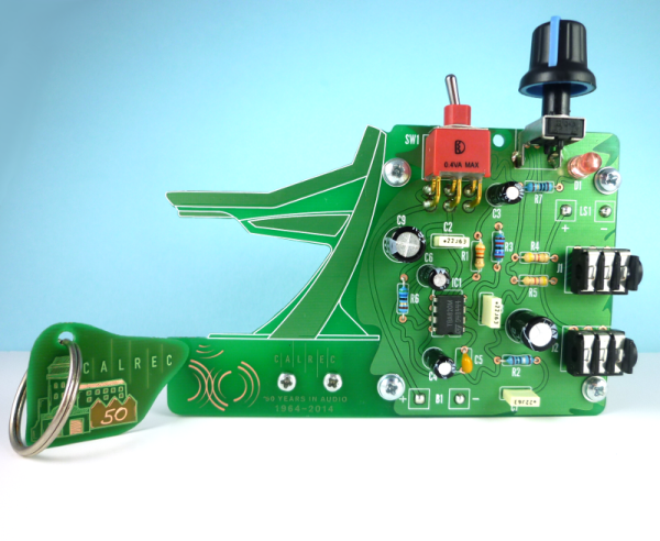
For the special occasion of their 50th anniversary, Calrec Audio contacted [Saar] requesting he create something a bit more enticing than their standard rectangular design from previous years. With their schematic as a starting point, [Saar] used cardboard to mock-up a few of his ideas in order to get a feel for the placement of the components. Several renditions later, [Saar] decided to implement the exact proportions of the company’s iconic Apollo desk into the heart of the design as an added nod back to the company itself. In the negative space between the lines of the Apollo desk there is a small perforated piece depicting the mill where the Calrec offices are located. The image of the mill makes use of different combinations of copper, silk and solder mask either absent or present to create shading and depth as the light passes through the board. This small piece that would have otherwise been removed as scrap can be snapped off from the body of the PCB and used as a commemorative keychain.

With the battery and speaker mounted behind the completed circuit board, [Saar’s] design succeeds in being a unique memento with a stylish appeal. There is a complete case study with detailed documentation on the Nutclough from cardboard to product on the Boldport website. Here you can also see some other examples of their gorgeous circuit art, or checkout their opensource software to help in designing your own alternative PCBs.