laser keyboard

MIDI Keyboard With Frickin’ Laser Keys

MIDI instruments are cool, but they’re not laser cool. That is, unless you’ve added lasers to your MIDI instrument like [Lasse].

[Lasse] started out with an old MIDI keyboard. The plan was to recycle an older keyboard rather than have to purchase something new. In this case, the team used an ESi Keycontrol 49. They keyboard was torn apart to get to the creamy center circuit boards. [Lasse] says that most MIDI keyboards come withe a MIDI controller board and the actual key control board.

Once the key controller board was identified, [Lasse] needed to figure out how to actually trigger the keys without the physical keyboard in place. He did this by shorting out different pads while the keyboard was hooked up to the computer. If he hit the correct pads, a note would play. Simple, but effective.

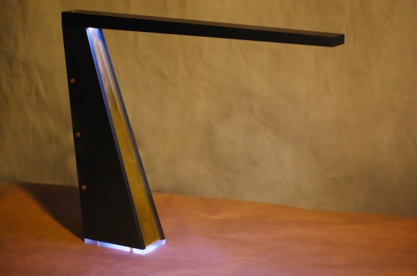
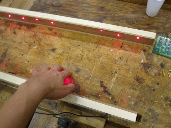
The housing for the project is made out of wood. Holes were drilled in one piece to mount 12 laser diodes. That number is not arbitrary. Those familiar with music theory will know that there are 12 notes in an octave. The lasers were powered via the 5V source from USB. The lasers were then aimed at another piece of wood.

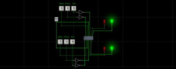
Holes were drilled in this second piece wherever the lasers hit. Simple photo resistors were mounted here. The only other components needed for each laser sensor were a resistor and a transistor. This simple discreet circuit is enough to simulate a key press when the laser beam is broken. No programming or microcontrollers required. Check out the demonstration video below to see how it works. Continue reading “MIDI Keyboard With Frickin’ Laser Keys”

Tripping On Oscilloshrooms With An Analog Scope

This might be an old trick, but it’s still cool to see a functional tool like the oscilloscope manipulated for an unrelated purpose such as this. [Jerobeam Fenderson] made a video explaining how to input stereo audio into an old digital scope in order to create of all things, dancing mushrooms… because why not?

In this case, [Jerobeam] used a Tektronix D11 5103N set in X Y mode and attached the left and right channels from his RME Fireface UC audio interface. One channel corresponds with X, and the other with Y. From here, he controls the wave forms discretely with the help of software like Pure Data (Pd) and Max (not free, but more powerful) which are visual programming environments made to enable musicians and artists to create software without writing lines of code. His video explains how to make a circle out of a sine wave, and then beat the crap out of it with math far beyond our comprehension. The outcome is pretty mesmerizing and leaves us wanting to try it out ourselves. Luckily, if you’re interested in experimenting with the voice of sine waves… [Jerobeam] has more information on his blog on how to do some scope play of your own whether your hardware is analog or digital.

You can see the dancing mushrooms in his video below:

Continue reading “Tripping On Oscilloshrooms With An Analog Scope”

Logic Simulator Atanua Goes Free, Possibly Open Source

The history of software is littered with developers that built a great product, gave people a reasonable option to license the software, and ended up making a pittance. There’s a reason you don’t see shareware these days – nobody pays. It looks like [Gates] had a point with his Open Letter to Hobbyists.

Such is the case with Atanua. [Jari] built a nice little graphical logic simulator that has tens of thousands of downloads, and is being used in dozens of universities. [Jari] has sold only about 60 licenses for Atanua, netting him only a few thousand Euro. You can’t develop software with a pittance, so now [Jari] is giving Atanua away. This neat little logic simulator has reached the end of its life, the license is free, and [Jari] is out of the business.

This isn’t an ideal situation, but [Jari] is strongly considering open-sourcing Atanua. The code is a little bit of a mess at the moment, and cleaning it up will require a bit of work. [Jari] is leaving the option to buy a license for Atanua open, and anyone who wants to see this bit of software open sourced could buy a license or hundred.

While this isn’t great news for [Jari], if you’re looking for a neat tool to learn digital logic, you now have a very nice free option. Atanua simulates individual logic gates, 74-series chips, and even an 8051 microcontroller in real-time (up to about 1 kHz), with enough buttons, LEDs, and displays to do some very cool stuff. It’s more than enough to learn digital logic on, and good enough for a test bed for some odd and bizarre projects you might have floating around your head.

3D Printed Lens

3D Printed Lenses Open Up Possibilities

Now this is some seriously cool stuff. The folks over at FormLabs decided to try a little experiment to test the optical clarity of their clear resin. It’s pretty damn clear.

Using their own slicing software, PreForm, [Craig Broady] printed the lens piece in an orientation that would maximize resin flow around the lens to help prevent defects, keeping it as smooth as possible. While the printed part looks quite clear, all lenses require some form of polishing to become optically clear. It was printed with a 50 micron resolution, and [Craig] used a power drill to sand the lens down from 220 grit to 2000 grit sand paper.

Continue reading “3D Printed Lenses Open Up Possibilities”

Desk lamp

Sleek Desk Lamp Changes Colors Based On Sun Position

[Connor] was working on a project for his college manufacturing class when he came up with the idea for this sleek desk lamp. As a college student, he’s not fond of having his papers glowing brightly in front of him at night. This lamp takes care of the problem by adjusting the color temperature based on the position of the sun. It also contains a capacitive touch sensor to adjust the brightness without the need for buttons with moving parts.

The base is made from two sheets of aluminum and a bar of aluminum. These were cut and milled to the final shape. [Connor] found a nice DC barrel jack from Jameco that fits nicely with this design. The head of the lamp was made from another piece of aluminum bar stock. All of the aluminum pieces are held together with brass screws.

A slot was milled out of the bottom of the head-piece to make room for an LED strip and a piece of 1/8″ acrylic. This piece of acrylic acts as a light diffuser.  Another piece of acrylic was cut and added to the bottom of the base of the lamp. This makes for a nice glowing outline around the bottom that gives it an almost futuristic look.

The capacitive touch sensor is a pretty simple circuit. [Connor] used the Arduino capacitive touch sensor library to make his life a bit easier. The electronic circuit really only requires a single resistor between two Arduino pins. One of the pins is also attached to the aluminum body of the lamp. Now simply touching the lamp body allows [Connor] to adjust the brightness of the lamp.

[Connor] ended up using an Electric Imp to track the sun. The Imp uses the wunderground API to connect to the weather site and track the sun’s location. In the earlier parts of the day, the LED colors are cooler and have more blues. In the evening when the sun is setting or has already set, the lights turn more red and warm. This is easier on the eyes when you are hunched over your desk studying for your next exam. The end result is not only functional, but also looks like something you might find at that fancy gadget store in your local shopping mall.

USB On The Teensy 3 From The Ground Up

When implementing USB on a microcontroller, most people are going to reach for V-USB if they’re using an AVR, one of Microchip’s USB libraries if a PIC is involved, or any number of the USB libraries for various ARM processors. [Kevin] had a different idea. As a challenge to himself, he wrote a USB device driver for the Teensy 3.1 microcontroller board, getting as close to the bare metal as he could get.

Writing a USB device driver first required a literature review. There are a few peculiarities in the Freescale K20 family of microcontrollers – the one found in the Teensy 3.1 – that dictate the need for a specific memory layout, using several clocks, and handling all the USB descriptors. [Kevin] started with the clocks, every last one of which must be enabled. The clock is generated by the Multipurpose Clock Generator from a 16MHz crystal, PLL’ed to the frequencies the USB module needs, and sent out over the System Integration Module.

Following the flowcharts and sequences found in the Freescale reference guide told [Kevin] exactly what needed to be done with the startup sequence, and offered a few suggestions on what needed to be done to set up all the interrupts. [Kevin] spent an incredible amount of time documenting, programming, and smashing his head against the keyboard for this tutorial, but he does give everyone a great opportunity to learn from his struggles.

While [Kevin] has a mostly complete USB device driver, his work is far from done. That’s alright, because this project wasn’t meant to be a full-featured driver; it’s still missing real error handling, strings in the configuration, and a real VID/PID. That’s alright, it’s still a great exercise in building something from scratch, especially something that very few people have built successfully.

Oh, blatant Hackaday Store plug for the Teensy 3.1.

2014 Advent Calender Of Circuits

Every day this month and until Christmas, [vk2zay] is (has already been!) posting a simple but useful hack in his 2nd sort-of-annual “Advent Calender of Circuits” that many of you will want to be bookmarking. For those already saturated with the season of holiday hacks, don’t worry – other than being festively generous of him to tutor and demo a new hack every day, the hacks themselves have nothing to do with Christmas. Though he missed the last couple years we here at Hackaday covered his first month of hacks back in 2011 (now in playlist).

The daily hacks posted so far cover a wide variety of useful projects (leaning towards HV) for the electronics hobbyist who might not have all the fancy tools in their shop: DIY high voltage probes, a 1-hour tesla coil from junk, measuring RF power, a stud detector, how to test an  unknown transformer’s saturation, and many others. We cannot predict what will be posted the rest of the calender (the author hints to be making them up as he goes), but by now it is safe to say that they will not disappoint.

We would be stealing his thunder to cover them all, so, we will just pick our favorite for now:

The 1-hour tesla coil is a delightful all-shortcuts-taken hack project. If one were to listen to aficionados, teslacoiling is a highly precise hobby to get into. It appears to require careful planning, much calculation, special-ordered or soviet-surplus parts, custom jigs, fine tuning, etc. [vk2zay] shows otherwise.

Every single component of the assembly is itself a hack.

No fancy tungsten-infused grade 8 copper being water-cooled via heat pump here – the spark gap is just the bent leg of a capacitor hovering near the start of the primary winding. The power supply is a backlight inverter with a chain of Cockcroft-Walton voltage doublers. The high voltage resistor is a bunch of series-chained resistors shoved into a silicone tube. The topload is a couple cheap pie tins masking-taped together to “resemble something like a sphere.” The primary is a loose, unsupported spring of copper wire. The secondary was calculated to be whatever the height of the tube he had handy and coiled only as smoothly as a first attempt would allow. He does not even bother using wires or a switch – the circuit is completed by clipping a couple of test leads.

After all this hodgepodgery the circuit was then carefully tuned to optimize how little time it took to build (additional time used: zero). Since the frequencies do not match (1.7 vs. 2.6 mhz – 35% apart) the only thing this circuit resonates with is a hacker’s appeal for making do. Does not matter, still works. The streamers easily reach 2 inches and the author claims double that in dark lighting.

In the just 6 minute video he also manages to explain roughly what is going on theory-wise and suggest the time-effective things to considering upgrading. Almost a dozen hacks in the bag and over a dozen more to come before Christmas.

Continue reading “2014 Advent Calender Of Circuits”